PICBASIC
PLUS LITE
COMPILER
Please
Note.
The LITE
version of the PICBASIC PLUS compiler offers an opportunity to write a program
for the PIC first hand. See for yourself how powerful and easy to use the compiler really is.
The LITE
version is limited to 20 lines of code, with only one commnand per line, as
opposed to multiple commands, and unlimited lines in the full version. Anmother
limitation is the type of PIC supported. The LITE version is compatable with
the ever-popular 16F84 and 16F877 devices, with crystal frequencies of 4MHz and
20MHz only. The full version is compatable with all the 14-bit core devices, and
6 crystal frequencies. Another limitation is the lack of any graphic LCD commands.
Other than that, the compiler is fully operational.
Although every precaution has been taken with the preparation of this manual to ensure that any projects, designs or programs enclosed, operate in a correct and safe manner. The author and publisher assume no responsibility for errors or omissions. Neither is any liability assumed for the failure of any project, design or program, or any damage caused to equipment that it may be connected to, or used in combination with.
Copyright Crownhill Associates. All right reserved. No part of this publication may be reproduced, stored in a retrieval system, or distributed in any form or by any means without the written permission of the publisher or author.
The Microchip logo and name are registered trademarks of Microchip Technologies Inc.
The EPICtm programmer is a trade name of microEngineering Labs inc.
PICBASIC PLUS is a trade name of Crownhill Associates.
Published and distributed by Crownhill Associates Ltd
Author Les Johnson.
First Edition August 2001.
Table of Contents.
3.10. Ports and Other Registers
5 - PICBASIC PLUS
Commands and Directives. 22
6 - Incorporating Assembler into a BASIC program.
Special instruction mnemonics.
7.1. Using the on-board
Programmer
The PICBASIC PLUS compiler was written with simplicity and flexibility in mind. Using BASIC, which is almost certainly the easiest programming language around, you can now produce extremely powerful applications for your PIC without having to learn the relative complexity of assembler. Having said this, we have included various ‘enhancements’ for extra versatility and ease of use in the event that assembler is required.
PICBASIC PLUS provides a seamless development environment, found with no other PIC BASIC compiler, With PICBASIC PLUS , you can write, debug and compile your code within the same Windows environment, and by using a compatible programmer, just one key press allows you to program and verify the resulting code in the PIC of your choice!
It should be noted that PICBASIC PLUS is NOT code compatible with the popular Parallax PICBASIC, which is a proprietary language, specific to their BASIC Stamp Parts.
1.1. PIC Devices
The devices supported by this software are the most commonly used and the compiler takes advantage of their various features e.g. The A/D converter in the 16F87x series, the data memory eeprom area in the 16C84 and 16F84. This manual is not intended to give you details about PIC devices Therefore for further information, visit the Microchip website at www.microchip.com, and download the multitude of datasheets available.
Because of the limited architecture of the 12-bit devices, the compiler is only compatible with the 14-bit core types. This isn’t such a limitation, as the 16C55x range of devices may be used instead of the original 16C5x devices. If an 8-pin device is required, the incredibly flexible 12C67x range may be used.
1.2. PICBASIC PLUS Discussion
For your convenience we have set up a web site www.letbasic.com, where there is a section for users of PICBASIC to discuss the compiler, and provide self help with programs written for PICBASIC, or download sample programs. The web site is well worth a visit now and then either to learn a bit about how other peoples code works or to request help should you encounter any problems with programs that you have written.
To become a member of the discussion list, send an email to: -
majordomo@qunos.net
In the message body enter: -
subscribe LETBASIC-L
This will then reply with a message to verify your email address and ask you to reply. Once this is done, messages may be sent to: -
letbasic-l@qunos.net
1.4. Contact Details
Should you need to get in touch with us for any reason our details are as follows: -
Postal: Crownhill Associates Limited
32 Broad Street
Ely, Cambridgeshire
CB4 4AH
Telephone: UK: 01353 666709
Int: +44 1353 666709
Fax: UK: 01353 666710
Int: +44 1353 666710
Email: Sales@crownhill.co.uk
Web Site: http://www.crownhill.co.uk
http://www/letbasic.com
2.1. Installing the software
Using Windows explorer, change to your CD and locate the program called setup or setup.exe this is the main install application. Double‑click this and follow the on-screen prompts.
Note, the software is now fully installed on your hard drive so there is no need to put the CD in when you want to run it.
2.2. Ready to start ?
Once
the compiler is run you will be presented with an editor. This allows BASIC
code to be written, compiled, then programmed using one of many programmers.
The editor implements syntax highlighting for ease of use. All keywords,
numbers, comments etc have a different colour representing them.
|
|
|
|
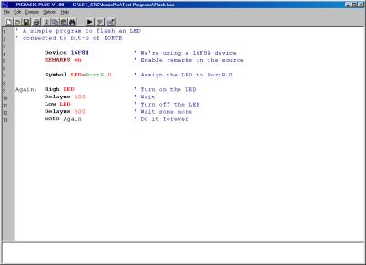
The
editor window above, shows a simple program for flashing an LED.
The
program is compiled by clicking on the Compile button, ![]() or right clicking the mouse and choosing Compile. The program
will then be compiled and assembled, and if there are no errors in the code,
the Program button will be enabled. Any errors will be displayed on the
bottom window, along with the offending line or lines.
or right clicking the mouse and choosing Compile. The program
will then be compiled and assembled, and if there are no errors in the code,
the Program button will be enabled. Any errors will be displayed on the
bottom window, along with the offending line or lines.
As
an example of your first piece of code, enter the following program: -
DEVICE
16F84
DECLARE
XTAL 4
SYMBOL
LED = PORTB.0
Again: HIGH LED
DELAYMS 500
LOW LED
DELAYMS 500
GOTO Again
This
will flash an LED connected to bit-0 of PORTB.
Once
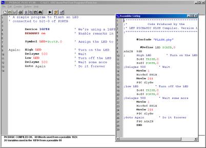
the compile button is pressed, the following text should be displayed in the
bottom window: -
PICBASIC COMPILED OK. 60 Words used from a possible 1024
26 Variables used in the
16F84 from a possible 68
The
text is pretty much self explanatory in that it informs you that 60 words are
used in the 16F84 device, which has 1024 (1K) of available program memory. The
same is true for the variables used. The word ‘variable’ is used to indicate
RAM memory, therefore if a WORD size variable is used in the program, it will
require two RAM locations. Even though the flashing LED program didn’t declare
any variables, the compiler always uses a minimum of 26 RAM locations, these
are it’s system variables.
To
view the assembler code produced, click on the View button ![]() A new window will appear displaying the
assembled source code.
A new window will appear displaying the
assembled source code.
|
|
|
|
The code may now be
programmed into the PIC by clicking the program button ![]() ,
see section seven for details of the choices of programmer.
,
see section seven for details of the choices of programmer.
2.3. Customising the editor.
The editor itself may be
customised to a certain degree by choosing File->Editor Options. You
will be presented with an options box that allows the syntax colours to be
altered along with how the editor handles tabs etc: -
|
|
|
|
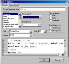
All
the new settings are remembered by the compiler, so there’s no need to alter them
every time the editor is opened.
As with any language,
there are rules you must follow when producing a program and PICBASIC PLUS is no exception. These are laid out in this
section.
3.1. Device specific issues.
Before venturing into
your latest project, always read the datasheet for the specific device being
used. Because some devices have features that may interfere with expected pin
operations. The PIC16C62x and the 16F62x devices are examples of this. These
PICmicros have analogue comparators on PORTA. When these chips first power up,
PORTA is set to analogue mode. This makes the pin functions on PORTA work in a
strange manner. To change the pins to digital, simply add the following line
near the front of your BASIC program, or before any of the pins are accessed: -
CMCON =
7
Any PICmicro with
analogue inputs, such as the PIC16C7xx, PIC16F87x and PIC12C67x series devices,
will power up in analogue mode. If you intend to use them as digital types you
must set the pins to digital by using the following line of code: -
ADCON1 =
7
Another example of
potential problems is that bit-4 of PORTA (PortA.4) exhibits unusual behaviour
when used as an output. This is because the pin has an open drain output rather
than the usual bipolar stage as in the rest of the output pins. This means it
can pull to ground when set to 0 (low), but it will simply float when set to a
1 (high), instead of going high.
To make this pin act as
expected, add a pull-up resistor between the pin and 5 Volts. A typical value
resistor may be between 1K and 33K, depending on the device it is driving. If
the pin is used as an input, it behaves the same as any other pin.
Some PICmicros, such as the PIC16F87x range, allow
low-voltage programming. This function takes over one of the PORTB (PortB.3)
pins and can cause the device to act erratically if this pin is not pulled low.
In normal use, It’s best to make sure that low-voltage programming is disabled
at the time the PICmicro is programmed. By default, the low voltage programming
fuse is disabled, however, if the CONFIG directive is used, then it may
inadvertently be omitted.
All of the PICmicro pins are set to inputs on
power-up. If you need a pin to be an output, set it to an output before you use
it, or use a BASIC command that does it for you. Once again, always read the
PICmicro data sheets to become familiar with the particular part.
The name of the port pins on the PIC12C67x and
12CE67x devices is GPIO. The name for the TRIS register is TRISIO: -
GPIO.0 = 1 ‘ Set GPIO.0 high
TRISIO = %101010 ‘ Manipulate ins and outs
3.2. Identifiers
An identifier is a
technical term for a name. Identifiers are used in PICBASIC PLUS for line labels, variable names, and
constant aliases. An identifier is any sequence of letters, digits, and
underscores, although it must not start with a digit. Identifiers are not case
sensitive, therefore label, LABEL, and Label are all treated as equivalent. And
while labels might be any number of characters in length, only the first 32 are
recognised.
3.3. Line Labels
In order to mark
statements that the program may wish to reference with the GOTO, CALL,
or GOSUB commands, PICBASIC PLUS
uses line labels. Unlike many older BASICs, PICBASIC PLUS doesn't allow or require line numbers and
doesn't require that each line be labelled. Instead, any line may start with a
line label, which is simply an identifier followed by a colon ‘:’.
Lab:
PRINT “Hello World”
GOTO
Lab
3.4. Variables
Variables are where
temporary data is stored in a BASIC program. They are created using the DIM
keyword. Because RAM space on PICmicros is somewhat limited in size, choosing
the right size variable for a specific task is important. Variables may be
bits, bytes or words. Space for each variable is automatically allocated in the
micro controller’s RAM area. The format for creating a variable is as follows:
-
DIM
Label as Size
Label is
any identifier, (excluding keywords). Size is BIT, BYTE or
WORD. Some examples of creating variables are: -
DIM
Dog as BYTE ‘ Create an 8-bit variable (0-255)
DIM
Cat as BIT ‘ Create a single bit variable (0-1)
DIM
Rat as WORD ‘ Create a 16-bit variable (0-65535)
The number of variables
available depends on the amount of RAM on a particular device and the size of
the variables within the BASIC program. PICBASIC PLUS reserves approximately 26 RAM locations for its own use. It may
also create additional temporary variables for use when calculating complex
equations.
There
are certain reserved words that cannot be used as variable names, these are the
system variables used by the compiler.
The
following reserved words cannot be used as variable names: -
PP0, PP0H, PP1, PP1H, PP2, PP2H, PP3, PP3H, PP4, PP4H, PP5, PP5H,
PP6, PP6H, PP7, PP7H, GEN, GENH, GEN2, GEN2H, GEN4, GEN4H, GPR, BPF.
3.5. Aliases
DIM
can also be used to create an alias to a variable. This is very useful for
accessing the separate parts of a variable.
DIM
Fido as Dog ‘ Fido is another name for Dog
DIM
Mouse as Rat.LOWBYTE ‘ Mouse is the first byte (low byte) of word Rat
DIM
Tail as Rat.HIGHBYTE ‘ Tail
is the second byte (high byte) of word Rat
DIM
Flea as Dog.0 ‘ Flea is bit-0 of Dog
3.6. Constants
Named constants may be created in the same manner
as variables. It can be more informative to use a constant name instead of a constant
number. Once a constant is declared, it cannot be changed later, hence the name
‘constant’.
DIM Label as Constant
expression
DIM Mouse as 1
DIM Mice as Mouse * 400
3.7. Symbols
SYMBOL provides yet another
method for aliasing variables and constants. SYMBOL cannot be used to
create a variable. Constants declared using SYMBOL do not use any RAM
within the PIC.
SYMBOL Tiger = cat ‘ Cat was previously created using DIM
SYMBOL Mouse = 1 ‘ Same as DIM Mouse as 1
SYMBOL
Tigouse = Tiger + Mouse ‘ Add Tiger to Mouse to make Tigouse
If
a variable or register’s name is used in a constant expression then the
variable’s or register’s address will be substituted, not the value held in the
variable or register: -
SYMBOL
CON = (PORTA + 1) ‘ CON will
hold the value 6 (5+1)
SYMBOL
is also useful for aliasing Ports and Registers: -
SYMBOL LED = PORTA.1 ‘ LED now references bit-1 of PortA
SYMBOL T0IF = INTCON.2 ‘ T0IF now references bit-2 of INTCON register
The
equal sign between the Constant’s name and the alias value is optional: -
SYMBOL LED PORTA.1 ‘ Same as SYMBOL LED=PORTA.1
3.8. Numeric Representations
PICBASIC
PLUS recognises four different number
representations: -
Binary
is prefixed by %. i.e. %0101
Hexadecimal
is prefixed by $. i.e. $0A
Character
byte is surrounded by quotes. i.e. “a” represents a value of 97
Decimal values need no prefix.
3.9. String Constants
PICBASIC PLUS
doesn't provide conventional string handling capabilities, but strings
can be used with some commands. A string contains one or more characters and is
delimited by double quotes.
PRINT "Hello
World" ‘ Output String
("H","e","l","l","o",”
“,"W","o","r","l","d")
Strings are usually treated as a list of individual
character values, and are used by commands such as PRINT, RSOUT, BUSOUT,
EWRITE etc.
3.10. Ports and Other Registers
All of the PICmicro registers, including the ports,
can be accessed just like any other byte-sized variable. This means that they
can be read from, written to or used in equations directly:
PORTA = %01010101 ‘ Write value to PORTA
Var = Wrd * PORTA ‘ Multiply variable WRD with the contents of PORTA
3.11. General Format
The
compiler is not case sensitive, except when processing string constants such as
“hello”.
Multiple
instructions and labels can be combined on the same line by separating them
with colons ‘:’.
The
examples below show the same program as separate lines and as a single-line...
Multiple-line
version: -
TRISB = %00000000 ' Make all pins on PortB outputs
FOR
Var = 0 TO 100
' Count from 0 to 100
PORTB = Var ' Make PortB = count (Var)
NEXT ' Continue counting until 100 is reached
Single-line
version: -
TRISB = %00000000 :
FOR Var = 0 TO 100 : PORTB =
Var : NEXT
-----------------------------------------------------------------------------------------------------------------
The PICBASIC PLUS
Compiler performs all math operations in full hierarchal order. Which
means that there is precedence to the operators. For example, multiplies and
divides are performed before adds and subtracts. To ensure the operations are
carried out in the correct order use parenthesis to group the operations: -
A
= (( B – C ) * ( D + E )) / F
All
math operations are unsigned and performed with 16-bit precision.
The
operators supported are: -
+ Addition
- Subtraction
* Multiplication
**
Top
16 Bits of Multiplication
*/
Middle
16 Bits of Multiplication
/ Division
//
Remainder
(Modulus)
<<
Shift
Left
>>
Shift
Right
&
Bitwise
AND
| Bitwise OR
^ Bitwise XOR
4.1.
Addition ‘+’.
The
Addition operator (+) adds variables and/or constants, returning a 16-bit
result. Works exactly as you would expect with unsigned integers from 0 to
65535. If the result of addition is larger than 65535, the carry bit will be
lost.
DIM Value1 as WORD
DIM Value2 as WORD
Value1 = 1575
Value2 = 976
Value1 = Value1 + Value2 ' Add the numbers.
PRINT @Value1 ' Display the result
4.2.
Subtraction ‘-‘.
The
Subtraction operator (-) subtracts variables and/or constants, returning a
16-bit result. Works exactly as you would expect with unsigned integers from 0
to 65535.
DIM Value1 as WORD
DIM Value2 as WORD
Value1 = 1000
Value2 = 999
Value1 = Value1 - Value2 ' Subtract the numbers.
PRINT @Value1 ' Display the result
4.3.
Multiply ‘*’.
The
Multiply operator (*) multiplies variables and/or constants, returning the low
16 bits of the result. Works exactly as you would expect with unsigned integers
from 0 to 65535. If the result of multiplication is larger than 65535, the
excess bits will be lost.
DIM Value1 as WORD
DIM Value2 as WORD
Value1 = 1000
Value2 = 19
Value1 = Value1 * Value2 ' Multiply Value1 by Value2.
PRINT @Value1 ' Display the result
4.4.
Multiply HIGH ‘**’.
The
Multiply High operator (**) multiplies variables and/or constants, returning
the high 16 bits of the result. When multiplying two 16-bit values, the result
can be as large as 32 bits. Since the largest variable supported by the
compiler is 16-bits, the highest 16 bits of a 32-bit multiplication result are
normally lost. The ** (double-star) operand produces these upper 16 bits.
For example, suppose 65000 ($FDE8) is
multiplied by itself. The result is 4,225,000,000 or $FBD46240. The * (star, or
normal multiplication) instruction would return the lower 16 bits, $6240. The
** instruction returns $FBD4.
DIM Value1 as WORD
DIM Value2 as WORD
Value1 = $FDE8
Value2 = Value1 ** Value1 ' Multiply $FDE8 by itself
PRINT hex Value2 ' Return high 16 bits.
4.5.
Multiply MIDDLE ‘*/’.
The
Multiply Middle operator (*/) multiplies variables and/or constants, returning
the middle 16 bits of the 32-bit result. This has the effect of multiplying a
value by a whole number and a fraction. The whole number is the upper byte of
the multiplier (0 to 255 whole units) and the fraction is the lower byte of the
multiplier (0 to 255 units of 1/256 each). The */ operand allows a workaround
for the compiler’s integer-only math.
Suppose
we are required to multiply a value by 1.5. The whole number, and therefore the
upper byte of the multiplier, would be 1, and the lower byte (fractional part)
would be 128, since 128/256 = 0.5. It may be clearer to express the */
multiplier in HEX as $0180, since hex keeps the contents of the upper and lower
bytes separate. Here's an example:
DIM Value1 as WORD
Value1 = 100
Value1 = Value1 */ $0180 ' Multiply by 1.5 [1 + (128/256)]
PRINT @Value1 ' Show result (150).
To
calculate constants for use with the */ instruction, put the whole number
portion in the upper byte, then use the following formula for the value of the
lower byte: -
INT(fraction
* 256)
For
example, take Pi (3.14159). The upper byte would be $03 (the whole number), and
the lower would be INT(0.14159 * 256) = 36 ($24). So the constant Pi for use
with */ would be $0324. This isn’t a perfect match for Pi, but the error is
only about 0.1%.
4.6.
Divide ‘/’.
The
Divide operator (/) divides variables and/or constants, returning a 16-bit
result. Works exactly as you would expect with unsigned integers from 0 to 65535.
DIM Value1 as WORD
DIM Value2 as WORD
Value1 = 1000
Value2 = 5
Value1 = Value1 / Value2 ' Divide the numbers.
PRINT @Value1 ' Show the result (200).
4.7.
Modulus ‘//’.
The
Modulus operator (//) returns the remainder left after dividing one value by
another. Some division problems don’t have a whole-number result; they return a
whole number and a fraction. For example, 1000/6 = 166.667. Integer math
doesn’t allow the fractional portion of the result, so 1000/6 = 166. However,
166 is an approximate answer, because 166*6 = 996. The division operation left
a remainder of 4. The // returns the remainder of a given division operation.
Numbers that divide evenly, such as 1000/5, produce a remainder of 0: -
DIM Value1 as WORD
DIM Value2 as WORD
Value1 = 1000
Value2 = 6
Value1 = Value1 // Value2 ' Get remainder of Value1 / Value2.
PRINT @Value1 ' Show the result (4).
4.9. And ‘&’
The And operator (&) returns the bitwise
AND of two values. Each bit of the values is subject to the following logic: -
0 AND 0 = 0
0 AND 1 = 0
1 AND 0 = 0
1 AND 1 = 1
The
result returned by & will contain 1s in only those bit positions in which
both input values contain 1s: -
DIM Value1 as BYTE
DIM Value2 as BYTE
DIM Result as BYTE
Value1 = %00001111
Value2 = %10101101
Result = Value1 & Value2
PRINT bin Result ' Display AND result (%00001101)
or
PRINT bin (
%00001111 & %10101101
) ' Display
AND result (%00001101)
4.10. Or ‘|’
The OR operator (|) returns the
bitwise OR of two values. Each bit of the values is subject to the following
logic: -
0 OR 0 = 0
0 OR 1 = 1
1 OR 0 = 1
1 OR 1 = 1
The result returned by | will
contain 1s in any bit positions in which one
or the other (or both) input values
contain 1s: -
DIM Value1 as BYTE
DIM Value2 as BYTE
DIM Result as BYTE
Value1 = %00001111
Value2 = %10101001
Result = Value1 | Value2
PRINT bin Result ' Display OR result (%10101111)
or
PRINT bin ( %00001111 | %10101001 ) ' Display OR
result (%10101111)
4.11. Xor ‘^’
The Xor operator (^) returns the
bitwise XOR of two values. Each bit of the values is subject to the following
logic: -
0 XOR 0 = 0
0 XOR 1 = 1
1 XOR 0 = 1
1 XOR 1 = 0
The result returned by ^ will
contain 1s in any bit positions in which one or the other (but not both) input
values contain 1s: -
DIM Value1 as BYTE
DIM Value2 as BYTE
DIM Result as BYTE
Value1 = %00001111
Value2 = %10101001
Result = Value1 ^ Value2
PRINT bin Result ' Display XOR result (%10100110)
-- or --
PRINT bin ( %00001111 ^ %10101001 ) ' Display XOR result (%10100110)
-----------------------------------------------------------------------------------------------------------------
5 - PICBASIC
PLUS LITE Commands and Directives
ADIN Read on-chip analog to digital converter.
ASM-ENDASM Insert
assembly language code section.
BRANCH Computed GOTO (equiv. to ON..GOTO).
BRANCHL BRANCH out of page (long BRANCH).
BUSIN Read bytes from I2C device.
BUSOUT Write bytes to I2C device.
CALL Call assembly language subroutine.
CDATA Define initial contents in memory.
CLS Clear the LCD.
CONFIG Set or Reset
programming fuse configurations.
COUNTER Count
number of pulses on a pin.
CREAD Read word from code memory.
CURSOR Position the cursor on
the LCD.
CWRITE Write word to code memory.
DATA Define initial contents in memory.
DECLARE Adjust library routine
parameters.
DELAYMS Delay
(1mSec resolution).
DELAYUS Delay
(1uSec resolution).
DEVICE Choose the type of
PIC to compile with.
DIG Return the value of a decimal digit.
DIM Create a
variable.
EDATA Define initial contents of on-chip EEPROM.
END Stop execution.
EREAD Read byte or word from on-chip EEPROM.
EWRITE Write byte to on-chip EEPROM.
FOR…TO…NEXT…STEP Repeatedly execute statements.
GOSUB….RETURN Call BASIC subroutine at specified label.
GOTO Continue execution at specified label.
HIGH (or SET) Make pin, port, or register high.
IF…THEN…ELSE…ENDIF
Conditionally
execute statements.
INCLUDE Load a BASIC file into
the source code.
INKEY Scan a keypad.
INPUT Make pin an input.
[LET] Assign result of an expression to a variable.
LCDREAD Read
a single byte from a Graphic LCD. NOT
AVAILABLE IN LITE VERSION.
LCDWRITE Write
bytes to a Graphic LCD. NOT AVAILABLE IN LITE VERSION
LOOKDOWN Search
constant table for value.
LOOKDOWNL Search
constant / variable table for value.
LOOKUP Fetch constant value from table.
LOOKUPL Fetch
constant / variable value from table.
LOW (or CLEAR) Make pin, port, or register low.
ON_INTERRUPT Execute
a subroutine on a HARWARE interrupt.
OUTPUT Make
pin an output.
ORG Set
Program Origin.
PEEK Read byte from register.
PIXEL Read
a single pixel from a Graphic LCD. NOT AVAILABLE IN LITE VERSION
PLOT Set
a single pixel on a Graphic LCD. NOT AVAILABLE IN LITE VERSION
POKE Write byte to register.
POT Read potentiometer on specified pin.
PRINT Display characters on LCD.
PULSIN Measure pulse width on a pin.
PULSOUT Generate
pulse to a pin.
PWM Output pulse width modulated pulse train to pin.
RANDOM Generate a pseudo-random number.
RCIN Measure pulse width on a pin.
READ Read byte or word from memory.
REM Add a remark
to the source code.
REPEAT…UNTIL Execute statements until condition is true.
RESTORE Adjust the position of
data to READ.
RETURN Continue at statement following last GOSUB.
RSIN Asynchronous serial input from fixed pin and baud.
RSOUT Asynchronous serial output to fixed pin and baud.
SERVO Control a servo
motor.
SET_OSCCAL Calibrate the on-chip
oscillator.
SHIN Synchronous serial input.
SHOUT Synchronous serial output.
SNOOZE Power down processor for short period of time.
SLEEP Power down processor for a period of time.
SOUND Generate tone or white-noise on specified pin.
STOP Stop program execution.
SWAP Exchange the values of two variables.
SYMBOL Create an alias to a
constant, port, pin, or register
UNPLOT Clear
a single pixel on a Graphic LCD. NOT AVAILABLE IN LITE VERSION
WHILE…WEND Execute statements while condition is true.
-----------------------------------------------------------------------------------------------------------------
5.1. ADIN
Syntax : variable =
ADIN channel number
Overview : Read
the value from the on-board Analogue to Digital Converter.
Operators : Variable
is a user defined variable.
Channel number
can be a constant or a variable expression.
Example : ‘Read the value from channel 0 of the ADC and place in variable
Var.
DECLARE ADIN_RES 10 ‘ 10-bit result required
DECLARE ADIN_TAD FRC ‘ RC Osc chosen
DECLARE ADIN_STIME 50 ‘ Allow 50us sample time
DIM Var
as WORD
TRISA =
%00000001 ‘ Configure AN0 (PortA.0) as an input
ADCON1=%10000000 ‘ Set analogue input on PortA.0
Var=ADIN 0 ‘ Place the conversion into variable VAR
Declares : There
are three DECLARE directives for use with ADIN.
These are: -
DECLARE ADIN_RES 8 , 10 , or 12.
Sets the number of bits in the result.
If this DECLARE is not used, then the default is
the resolution of the PIC type used. For example, the new 16F87X range will
result in a resolution of 10-bits, while the standard PIC types will produce an
8-bit result. Using the above DECLARE allows an 8-bit result to be obtained
from the 10-bit PIC types, but NOT 10-bits from the 8-bit types.
DECLARE ADIN_TAD 2_FOSC , 8_FOSC , 32_FOSC , or FRC.
Sets the ADC’s clock source.
All compatible PICs have four options for the clock
source used by the ADC. 2_FOSC, 8_FOSC, and 32_FOSC, are ratios of the external
oscillator, while FRC is the PIC’s internal RC oscillator. Instead of using the
predefined names for the clock source, values from 0 to 3 may be used. These
reflect the settings of bits 0-1 in register ADCON0.
Care must be
used when issuing this DECLARE, as the wrong type of clock source may result in
poor resolution, or no conversion at all. If in doubt use FRC which will
produce a slight reduction in resolution and conversion speed, but is
guaranteed to work first time, every time. FRC is the default setting if the
DECLARE is not issued in the BASIC listing.
DECLARE ADIN_STIME 0 to 65535 microseconds (us).
Allows the internal capacitors to fully charge
before a sample is taken. This may be a value from 0 to 65535 microseconds
(us).
A value too small may result in a reduction of
resolution. While too large a value will result in poor conversion speeds
without any extra resolution being attained.
A typical value for ADIN_STIME is 50 to 100.
This allows adequate charge time without loosing too much conversion speed. But
experimentation will produce the right value for your particular requirement.
The default value if the DECLARE is not used in the BASIC listing is 50.
Notes
: Before the ADIN
command may be used, the appropriate TRIS register must be manipulated
to set the desired pin to an input. Also, the ADCON1 register must be
set according to which pin is required as an analogue input, and in some cases,
to configure the format of the conversion’s result. See the numerous Microchip
datasheets for more information on these registers and how to set them up
correctly for the specific device used.
If multiple conversions are being implemented, then a small delay should be used after the ADIN command. This allows the ADC’s internal capacitors to discharge fully: -
Again: Var = ADIN 3 ‘ Place the conversion into variable Var
DELAYUS 1 ‘ Wait for 1us
GOTO Again ‘ Read the ADC forever
See also : RCIN, POT
-----------------------------------------------------------------------------------------------------------------
5.2. ASM – ENDASM and @
Syntax : ASM
assembler mnemonics
ENDASM
or
@ assembler mnemonic
Overview
: Incorporate
in-line assembler in the BASIC code. The mnemonics are passed directly to the
assembler without the compiler interfering in any way. This allows a great deal
of flexibility that cannot always be achieved using BASIC commands alone.
The PICBASIC PLUS
compiler caters for using assembler like no other BASIC compiler
available. Because this is a rather detailed subject, section 6 has been
specially written to answer some of your questions and illustrate how assembler
mnemonics may be used with the compiler.
-----------------------------------------------------------------------------------------------------------------
5.3. BRANCH
Syntax : BRANCH Index,
[Label1 {,...Labeln }]
Overview
: Cause
the program to jump to different locations based on a variable index. On a PIC
device with only one page of memory.
Operators : Index is a constant,
variable, or expression, that specifies the address to branch to.
Label1,...Labeln
are valid labels that specify where to branch to.
Example
: DEVICE 16F84
DIM index as BYTE
Start: index
= 2 ‘assign index a value of 2
‘jump to label 2 (Lab_2) because index =
2
BRANCH index,[Lab_0, Lab_1,
Lab_2]
Lab_0: index
= 2 ‘index now equals 2
GOTO Start
Lab_1: index
= 0 ‘index now equals 0
GOTO Start
Lab_2: index
= 1 ‘index now equals 1
GOTO Start
The above example we first assign the index
variable a value of 2, then we define our labels. Since the first position is
considered 0 and the variable index equals 2 the BRANCH command will
cause the program to jump to the third label in the brackets [Lab2].
Notes : BRANCH is similar to the ON x GOTO
command found in other BASICs. It’s useful when you want to organise a
structure such as: -
IF Var = 0 THEN GOTO Lab_0 ' Var =0: go to label
"Lab_0"
IF Var = 1 THEN GOTO Lab_1 ' Var =1: go to label
"Lab_1"
IF Var = 2 THEN GOTO Lab_2 ' Var =2: go to label
"Lab_2"
You can use BRANCH to organize
this into a single statement: -
BRANCH Var, [Lab_0 , Lab_1, Lab_2]
This works exactly the same as the
above IF...THEN example. If the value is not in range (in this
case if Var is greater than 2), BRANCH does nothing. The program continues
with the next instruction..
The BRANCH command is primarily for use with
PIC devices that have one page of memory (0-2047). If larger PIC’s are used and
you suspect that the branch label will be over a page boundary, use the BRANCHL
command instead.
See
also : BRANCHL
-----------------------------------------------------------------------------------------------------------------
5.4. BRANCHL
Syntax : BRANCHL Index,
[Label1 {,...Labeln }]
Overview
: Cause
the program to jump to different locations based on a variable index. On a PIC
device with more than one page of memory.
Operators
: Index is a
constant, variable, or expression, that specifies the address to branch to.
Label1,...Labeln
are valid labels that specify where to branch to.
Example
: DEVICE 16F877
DIM index as BYTE
Start: index
= 2 ‘assigned index a value of 2
‘jump to label 2 (Lab2) because index =
2
BRANCHL index , [Lab0, Lab1,
Lab2]
Lab1: index
= 2 ‘index now equals 2
GOTO Start
Lab2: index
= 0 ‘index now equals 0
GOTO Start
Lab3: index
= 1 ‘index now equals 1
GOTO Start
The above example we first assign the index
variable a value of 2, then we define our labels. Since the first position is
considered 0 and the variable index equals 2 the BRANCHL command will
cause the program to jump to the third label in the brackets [Lab2].
Notes
: The BRANCHL
command is mainly for use with PIC devices that have more than one page of
memory (greater than 2048). It may also be used on any PIC device, but does
produce code that is larger than BRANCH.
See
also : BRANCH
-----------------------------------------------------------------------------------------------------------------
5.5. BUSIN
Syntax : Variable = BUSIN Control
, { Address }
or
BUSIN Control
, { Address }, [ Variable {, Variable…} ]
Overview
: Receives
a value from the I2C bus and places it into variable/s. By
first sending the control and optional address out of the clock
pin (SCL), and data pin (SDA).
Operators : Variable is
a user defined variable or constant.
Control
may be a constant value or a BYTE sized variable expression.
Address
may be a constant value or a variable expression.
The two variations of the BUSIN command may
both be used in the same BASIC program. The first type is useful for simply
receiving a single value from the bus. The second type may be used to receive
several values and designate each to a separate variable.
The BUSIN command operates as an I2C
master and may be used to interface with any device that complies with the 2-wire
I2C protocol.
The most significant 7-bits of control byte
contain the control code and the slave address of the device being interfaced
with. Bit-0 is the flag that indicates whether a read or write command is being
implemented.
For example, if we were interfacing to an external
eeprom such as the 24C32, the control code would be %10100001 or $A1. The most
significant 4-bits (1010) are the eeprom’s unique slave address. Bits 2 to 3
reflect the three address pins of the eeprom. And Bit-0 is set to signify that
we wish to read from the eeprom. Note that this bit is automatically set by the
BUSIN command, regardless of its initial setting.
Example : ‘ Receive a byte from the I2C bus and place it into
variable Var.
DIM Var
as BYTE ‘ We’ll
only read 8-bits
DIM Address
as WORD ‘ 16-bit address
required
SYMBOL Control
%10100001 ‘ Target an eeprom
Address = 20 ‘ Read the value at address 20
Var = BUSIN Control
, Address ‘
Read the byte from the eeprom
or
BUSIN Control
, Address, [ Var ] ‘ Read the byte from the eeprom
Address, is an optional
parameter that may be an 8-bit or 16-bit value. If a variable is used in this
position, the size of address is dictated by the size of the variable
used (BYTE or WORD). In the case of the previous eeprom interfacing, the 24C32
eeprom requires a 16-bit address. While the smaller types require an 8-bit
address. Make sure you assign the right size address for the device interfaced
with, or you may not achieve the results you intended.
The value received from the bus depends on the size
of the variables used. For example: -
DIM Wrd as WORD ‘ Declare a WORD size variable
Wrd = BUSIN Control , Address
Will receive a 16-bit value from the bus. While: -
DIM Var as BYTE ‘ Declare a BYTE size variable
Var = BUSIN Control , Address
Will receive an 8-bit value from the bus.
Using the second variation of the BUSIN
command allows differing variable assignments. For example: -
DIM
Var as BYTE
DIM
Wrd as WORD
BUSIN
Control , Address , [ Var , Wrd ]
Will receive two values from the bus, the first
being an 8-bit value dictated by the size of variable VAR which has been
declared as a byte. And a 16-bit value, this time dictated by the size of the
variable WRD which has been declared as a word. Of course, BIT type variables
may also be used, but in most cases these are not of any practical use as they
still take up a byte within the eeprom.
Declares : There
are three DECLARE directives for use with BUSIN.
These are: -
DECLARE SDA_PIN
PORT . PIN
Declares the
port and pin used for the data line (SDA). This may be any valid port on the
PIC. If this declare is not issued in the BASIC program, then the default Port
and Pin is PortA.0
DECLARE SCL_PIN
PORT . PIN
Declares the
port and pin used for the clock line (SCL). This may be any valid port on the
PIC. If this declare is not issued in the BASIC program, then the default Port
and Pin is PortA.1
These declares, as
is the case with all the DECLARES, may only be issued once in any single
program, as they setup the I2C library code at design time.
You may imagine that it’s limiting having a fixed
interface, but you must remember that several different devices may be attached
to a single bus, each having a unique slave address. Which means there is no
need to use up more than two pins on the PIC.
DECLARE SLOW_BUS ON - OFF
or 1 - 0
Slows the bus speed when using an oscillator higher
than 4MHz.
The standard speed for the I2C bus is
100KHz. Some devices use a higher bus speed of 400KHz. If you use an 8MHz or
higher oscillator, the bus speed may exceed the devices specs, which will
result in intermittent reads, or in some cases, no reads at all. Therefore, use
this DECLARE if you are not sure of the device’s spec. The datasheet for the device
used will inform you of its bus speed.
Notes : When the BUSIN command is used, the appropriate SDA and SCL Port and Pin are automatically setup for ins and outs.
Because the I2C protocol calls for an open-collector
interface, pull-up resistors are required on both the SDA and SCL lines. Values
of 4.7K to 10K Ohms will suffice.
See also : BUSOUT for suitable circuit, DECLARE
-----------------------------------------------------------------------------------------------------------------
5.6. BUSOUT
Syntax : BUSOUT Control
, { Address } , [ Variable {, Variable…} ]
Overview
: Transmit
a value to the I2C bus by first sending the control and
optional address out of the clock pin (SCL), and data pin (SDA).
Operators : Variable is
a user defined variable or constant.
Control
may be a constant value or a BYTE sized variable expression.
Address
may be a constant, variable, or expression.
The BUSOUT command operates as an I2C
master and may be used to interface with any device that complies with the
2-wire I2C protocol.
The most significant 7-bits of control byte
contain the control code and the slave address of the device being interfaced
with. Bit-0 is the flag that indicates whether a read or write command is being
implemented.
For example, if we were interfacing to an external
eeprom such as the 24C32, the control code would be %10100000 or $A0. The most
significant 4-bits (1010) are the eeprom’s unique slave address. Bits 2 to 3
reflect the three address pins of the eeprom. And Bit-0 is clear to signify
that we wish to write to the eeprom. Note that this bit is automatically
cleared by the BUSOUT command, regardless of its initial value.
Example : ‘ Send a byte to the I2C bus.
DIM Var
as BYTE ‘ We’ll
only read 8-bits
DIM Address
as WORD ‘ 16-bit address
required
SYMBOL Control
%10100000 ‘ Target an eeprom
Address = 20 ‘ Write to address 20
Var = 200 ‘ The value place into address 20
BUSOUT Control
, Address , [ Var ] ‘ Send the byte to the eeprom
DELAYMS 5 ‘ Allow time for allocation of byte
Address, is an optional
parameter that may be an 8-bit or 16-bit value. If a variable is used in this
position, the size of address is dictated by the size of the variable
used (BYTE or WORD). In the case of the above eeprom interfacing, the 24C32
eeprom requires a 16-bit address. While the smaller types require an 8-bit
address. Make sure you assign the right size address for the device interfaced
with, or you may not achieve the results you intended.
The value sent to the bus depends on the size of
the variables used. For example: -
DIM Wrd as WORD ‘ Declare a WORD size variable
BUSOUT Control , Address
, [ Wrd ]
Will send a 16-bit value to the bus. While: -
DIM Var as BYTE ‘ Declare a BYTE size variable
BUSOUT Control , Address
, [ Var ]
Will send an 8-bit value to the bus.
Using more than one variable within the brackets
allows differing variable sizes to be sent. For example: -
DIM
Var as BYTE
DIM
Wrd as WORD
BUSOUT
Control , Address , [ Var , Wrd ]
Will send two values to the bus, the first being an
8-bit value dictated by the size of variable VAR which has been declared as a
byte. And a 16-bit value, this time dictated by the size of the variable WRD
which has been declared as a word. Of course, BIT type variables may also be
used, but in most cases these are not of any practical use as they still take
up a byte within the eeprom.
A string of characters can also be transmitted, by
enclosing them in quotes: -
BUSOUT Control , Address
, [ “Hello World” , Var , Wrd ]
Declares : There
are four DECLARE directives for use with BUSOUT.
These are: -
DECLARE SDA_PIN
PORT . PIN
Assigns the port
and pin used for the data line (SDA). This may be any valid port on the PIC. If
this declare is not issued in the BASIC program, then the default Port and Pin
is PortA.0
DECLARE SCL_PIN
PORT . PIN
Assigns the port
and pin used for the clock line (SCL). This may be any valid port on the PIC.
If this declare is not issued in the BASIC program, then the default Port and
Pin is PortA.1
These declares,
as is the case with all the DECLARES, may only be issued once in any single
program, as they setup the I2C library code at design time.
You may imagine
that it’s limiting having a fixed interface, but you must remember that several
different devices may be attached to a single bus, each having a unique slave
address.
Which means there is no need to use up more
than two pins on the PIC.
DECLARE SLOW_BUS ON - OFF
or 1 - 0.
Slows the bus speed when using an oscillator higher
than 4MHz.
The standard speed for the I2C bus is
100KHz. However, some devices use a higher bus speed of 400KHz. If you use an
8MHz or higher oscillator, the bus speed may exceed the devices specs, which
will result in intermittent writes, or in some cases, no writes at all.
Therefore, use this DECLARE if you are not sure of the device’s spec. The
datasheet for the device used will inform you of its bus speed.
Notes : When the BUSOUT command is used, the appropriate SDA and SCL Port and Pin are automatically setup for ins and outs.
Because the I2C
protocol calls for an open-collector interface, pull-up resistors are
required on both the SDA and SCL lines. Values from 4.7KW to 10KW
will usually suffice.
See also : BUSIN
|
|
|
|
A typical use for the I2C commands is for interfacing with serial eeproms. The diagram shows the connections to the I2C bus of a 24C32 serial eeprom.
-----------------------------------------------------------------------------------------------------------------
5.7. CALL
Syntax : CALL
Label
Overview
: Execute
the assembly language subroutine named label.
Operators
: Label must
be a valid label name.
Example
: ‘ Call an assembler routine
CALL
Asm_Sub
ASM
Asm_Sub
{mnemonics}
Return
ENDASM
Notes
: The
GOSUB command is usually used to execute a BASIC subroutine. However, if
your subroutine happens to be written in assembler, the CALL command
should be used. The main difference between GOSUB and CALL is
that when CALL is used, the label’s existence is not checked
until assembly time. Using CALL, a label in an assembly language
section can be accessed that would otherwise be inaccessible to GOSUB.
This also means that any errors produced will be assembler types.
See also : GOSUB,
GOTO
-----------------------------------------------------------------------------------------------------------------
5.8. CDATA
Syntax : CDATA
{ alphanumeric data }
Overview
: Place
information directly into memory for access by CREAD and CWRITE.
Operators : alphanumeric data can be any alphabetic character or string enclosed in quotes (“) or numeric data without quotes.
Example : DEVICE
16F877 ‘ Use a
16F877 PIC
DIM
Var as BYTE
Var
= CREAD 2000 ‘ Read the
data from address 2000
ORG
2000 ‘ Set the address of the CDATA command
CDATA
120 ‘ Place 120 at address 2000
In
the above example, the data is located at address 2000 within the PIC, then
it’s read using the CREAD command.
Notes : CDATA is only available on the
newer PIC types that have self-modifying features, such as the 16F87x range.
In
order for the CREAD and CWRITE commands to locate the data in
memory, CDATA commands should be preceded by an ORG directive.
ORG
4000 ‘
Move the address pointer to 4000
CDATA
“Hello World” , 16200
, 253 ‘ Place the data at address 4000
The
above example, places the data “Hello World” at address 4000 within the PIC.
You must make sure that this area is not being used by your program. This can
be done by examining the last address in the HEX window.
An
alternative, and I think better, method for locating the address of the CDATA
table is by using a small ASM routine: -
DIM
Lab_Addr as WORD
' Get the address of CDATA LABEL into
variable Lab_Addr
@ Movlw High
Table ; Get hi address of table
Wreg_Byte Lab_AddrH ; Place into Variable
@ Movlw Low
Table ; Get lo address of table
Wreg_Byte Lab_Addr ; Place into Variable
{ rest of code }
Table:- CDATA { list of values }
By placing the above code at the
top of a program, the CDATA’s address is now held in the variable
LAB_ADDR.
This may
now be used in any expression, or more importantly, in the CWRITE and CREAD
commands. It also allows the CDATA table to be located anywhere in
memory without the use of the ORG directive.
Notice
the dash after the label’s name, this
disables any bank switching code that may otherwise disturb the location in
memory of the CDATA table. Also the use of the pseudo command WREG_BYTE,
this is explained in the ‘using assembler section’ of the manual.
The
configuration fuse setting WRTE must be enabled before CDATA, CREAD,
and CWRITE may be used. This enables the self-modifying feature. If the CONFIG
directive is used, then the WRTE_ON fuse setting must be included in the list:
-
CONFIG
WDT_ON , XT_OSC
, WRTE_ON
Because the 14-bit core devices are only capable of
holding 14 bits to a WORD, values greater than 16383 ($3FFF) cannot be stored.
See also : CONFIG,
CREAD, CWRITE, ORG
-----------------------------------------------------------------------------------------------------------------
5.9. CLS
Syntax : CLS
Overview
: Clears
the alphanumeric or graphic LCD and places the cursor at the home position i.e.
line 1, position 1
Example : CLS ‘ Clear the LCD
PRINT "HELLO" ‘ Display the word “HELLO” on the LCD
CURSOR 2 ,
1 ‘ Move the cursor to line 2, position 1
PRINT "WORLD" ‘
Display the word “WORLD” on the LCD
In the above example, the LCD is cleared using the CLS
command, which also places the cursor at the home position i.e. line 1,
position 1. Next, the word HELLO is displayed in the top left corner. The
cursor is then moved to line 2 position 1, and the word WORLD is displayed.
See also : CURSOR, DECLARE, see PRINT for an
LCD connection circuit.
-----------------------------------------------------------------------------------------------------------------
5.10. CONFIG
Syntax : CONFIG {
configuration fuse settings }
Overview
: Enable
or Disable particular fuse settings for the PIC type used.
Operators
: configuration fuse settings vary
from PIC to PIC, however, certain settings are standard to all PIC types. These
are: -
WDT_ON
Enable the internal Watchdog timer.
WDT_OFF
Disable the internal Watchdog timer.
HS_OSC
Use a High-speed crystal (Xtals over 4MHz) .
XT_OSC
Use a standard crystal (4MHz or under).
LP_OSC
Use a low frequency crystal (KHz range).
PWRTE_ON
Enable power up timer.
PWRTE_OFF
Disable power up timer.
Example : ‘ Disable the Watchdog timer and specify an HS_OSC
CONFIG WDT_OFF , HS_OSC
Notes
: If the CONFIG
directive is not used within the BASIC program then default values are used.
These may be found in the .LPB files in the INC folder.
Any fuse names
that are omitted from the CONFIG list will normally assume an OFF or
DISABLED state. However, this also applies to the OSC settings, therefore, if
no OSC fuse is indicated, then the default will be LP_OSC.
Before
programming the PIC, always check the fuse settings in the programmer window.
Always read the
datasheet for the particular PIC of interest, before using this directive.
-----------------------------------------------------------------------------------------------------------------
5.11. COUNTER
Syntax : Variable
= COUNTER Pin
, Period
Overview
: Count
the number of pulses that appear on pin during period, and store
the result in variable.
Operators : Variable is
a user-defined variable.
Pin
is a Port.Pin constant declaration i.e. PortA.0.
Period
may be a constant, variable, or expression.
Example : ‘ Count the pulses that occur on PortA.0 within a 100ms period
‘ and displays
the results.
DIM Wrd
as WORD ‘ Declare a word size variable
SYMBOL Pin
= PortA.0 ‘ Assign the input pin to PortA.0
CLS
Loop: Wrd=COUNTER
, Pin , 100 ‘ Variable
Wrd now contains the Count
CURSOR 1 , 1
PRINT dec
Wrd , “ “ ‘ Display
the decimal result on the LCD
GOTO Loop ‘ Do it indefinitely
Notes
: The
resolution of period is in milliseconds (ms). It obtains its scaling from the
oscillator declaration, DECLARE XTAL.
COUNTER checks the state
of the pin in a concise loop, and counts the rising edge of a transition (low
to high).
With a 4MHz oscillator, the pin is checked every
20us, and every 4us with a 20MHz oscillator. From this we can determine that
the highest frequency of pulses that may be counted is: -
25KHz using a 4MHz oscillator.
125KHz using a 20MHz oscillator.
See also : DECLARE
-----------------------------------------------------------------------------------------------------------------
5.12. CREAD
Syntax : Variable = CREAD Address
Overview
: Read
data from anywhere in memory.
Operators : Variable is
a user-defined variable.
Address is
a constant, variable, or expression, that represents any valid address within
the PIC.
Example : ‘ Read memory locations within
the PIC
DEVICE 16F877 ‘ Needs to be a 16F87x type PIC
DIM
Var as BYTE
DIM
Wrd as WORD
DIM
Address as WORD
Address=1000
‘ Address now holds the base address
Var
= CREAD 1000 ‘ Read 8-bit
data at address 1000 into Var
Wrd
= CREAD Address+10 ‘ Read
14-bit data at address 1000+10
Notes
: The CREAD
command takes advantage of the new self-modifying feature that is available in
the newer 16F87x range of devices.
If a WORD size
variable is used as the assignment, then a 14-bit WORD will be read. If a BYTE
sized variable is used as the assignment, then 8-bits will be read.
Because the
14-bit core devices are only capable of holding 14 bits to a WORD, values
greater than 16383 ($3FFF) cannot be read.
See CDATA
for an alternative method for locating the address of a CDATA table.
The
configuration fuse setting WRTE must be enabled before CDATA, CREAD,
and CWRITE may be used, this is the default setting. This enables the
self-modifying feature. If the CONFIG directive is used, then the
WRTE_ON fuse setting must be included in the list: -
CONFIG
WDT_ON , XT_OSC
, WRTE_ON
See
also : CDATA, CONFIG, CWRITE,
ORG
-----------------------------------------------------------------------------------------------------------------
5.13. CURSOR
Syntax : CURSOR
Line , Position
Overview : Move
the cursor position on the LCD to a specified line and position.
Operators
: Line is
a constant, variable, or expression that corresponds to the line number from 1
to maximum lines.
Position is
a constant, variable, or expression that moves the position within the line
chosen, from 1 to maximum position.
Example 1 : DIM
Line as BYTE
DIM
Xpos as BYTE
Line = 2
Xpos = 1
CLS ‘ Clear the LCD
PRINT "HELLO" ‘ Display the word “HELLO” on the LCD
CURSOR Line , Xpos ‘ Move the
cursor to line 2, position 1
PRINT "WORLD" ‘ Display the word “WORLD” on the LCD
In
the above example, the LCD is cleared using the CLS command, which also
places the cursor at the home position i.e. line 1, position 1. Next, the word
HELLO is displayed in the top left corner. The cursor is then moved to line 2
position 1, and the word WORLD is displayed.
Example
2 : DIM Xpos as BYTE
DIM Ypos as BYTE
Again: Ypos = 1 ‘ Start on line 1
FOR Xpos = 1 TO 16 ‘ Create a loop of
16
CLS ‘ Clear the LCD
CURSOR Ypos , Xpos ‘ Move the cursor
to position Ypos,Xpos
PRINT "*" ‘ Display the
character
DELAYMS 100
NEXT
Ypos = 2 ‘ Move to line 2
FOR Xpos = 16 TO 1 STEP -1 ‘ Create another
loop, this time reverse
CLS ‘ Clear the LCD
CUSROS Ypos , Xpos ‘ Move the cursor
to position Ypos,Xpos
PRINT "*" ‘ Display the
character
DELAYMS 100
NEXT
GOTO Again ‘ Repeat forever
Example 2
displays an asterisk character moving around the perimeter of a 2-line by 16
character LCD.
See also : CLS, see PRINT for an LCD
connection circuit
-----------------------------------------------------------------------------------------------------------------
5.14. CWRITE
Syntax : CWRITE Address
, [ Variable { , Variable…} ]
Overview
: Write
data to anywhere in memory.
Operators : Variable can
be a constant, variable, or expression.
Address is
a constant, variable, or expression that represents any valid address within
the PIC.
Example : ‘ Write to memory location
2000+ within the PIC
DEVICE 16F877 ‘ Needs to be a 16F87x type PIC
DIM
Var as BYTE
DIM
Wrd as WORD
DIM
Address as WORD
Address
= 2000 ‘ Address now holds the base address
Var
= 234
Wrd
= 1043
CWRITE
Address, [10, Var, Wrd ] ‘ Write to address 2000 +
ORG
2000
Notes
: The CWRITE
command takes advantage of the new self-modifying feature that is available in
the newer 16F87x range of devices.
If a WORD size
variable is used, then a 14-bit WORD will be written. If a BYTE sized variable
is used, then 8-bits will be written.
Because the
14-bit core devices are only capable of holding 14 bits to a WORD, values
greater than 16383 ($3FFF) cannot be written.
See CDATA
for an alternative method for locating the address of a CDATA table.
The
configuration fuse setting WRTE must be enabled before CDATA, CREAD,
and CWRITE may be used. This enables the self-modifying feature. If the CONFIG
directive is used, then the WRTE_ON fuse setting must be included in the list:
-
CONFIG
WDT_ON , XT_OSC
, WRTE_ON, LVPE_OFF
Take
care not to overwrite existing code when using the CWRITE commands, and
also remember that the all PICmicro devices have a finite amount of write
cycles (approx 1000). A single program can easily exceed this limit, making
that particular memory cell or cells inaccessible.
See also : CDATA, CONFIG, CREAD, ORG
-----------------------------------------------------------------------------------------------------------------
5.15. DATA
Syntax : DATA { alphanumeric
data }
Overview : Defines a table of alphanumeric data.
Operators : alphanumeric data can be any alphabetic character or string enclosed in quotes (“) or numeric data without quotes.
Example : DIM Var as BYTE
DATA 5 , 8 , ”fred” , 12
RESTORE
READ Var ‘ Variable Var will now contain the value 5
READ Var ‘ Variable Var will now contain the value 8
‘
Pointer now placed at location 4 in our data table i.e. “r”
RESTORE 3
‘ Var
will now contain the value 114 i.e. the ‘r’ character in decimal
READ Var
The data table is defined with the values 5,8,102,114,101,100,12 as “fred” equates to f:102, r:114, e:101, d:100 in decimal. The table pointer is immediately restored to the beginning of the table. This is not always required but as a general rule, it is a good idea to prevent table reading from overflowing.
The first READ Var, takes the first item of data from the table and increments the table pointer. The next READ Var therefore takes the second item of data. RESTORE 3 moves the table pointer to the fourth location (first location is pointer position 0) in the table - in this case where the letter ‘r’ is. READ Var now retrieves the decimal equivalent of ‘r’ which is 114.
Notes : DATA tables should be placed near the beginning of your program. Attempts to read past the end of the table will result in errors and unpredictable results.
Only one instance of DATA is allowed per program, however, they be of any length. If the alphanumeric contents of the DATA statement will not fit on one line then the extra information must be placed directly below using another DATA statement: -
DATA “HELLO ”
DATA “WORLD”
is the same as: -
DATA “HELLO WORLD”
See also: READ , RESTORE
-----------------------------------------------------------------------------------------------------------------
5.16. DECLARE
Syntax : DECLARE
code modifying directive , modifying value
Overview
: Adjust certain aspects
of the produced code, i.e. Crystal frequency, LCD port and pins, serial baud
rate etc.
Operators
: code modifying
directive is a set of pre-defined words. See list
below.
modifying value
is the value that corresponds to the command. See list below.
ADIN Declares.
DECLARE ADIN_RES
8 , 10 ,
or 12.
Sets the number of bits in the result.
If this DECLARE is not used, then the default is
the resolution of the PIC type used. For example, the new 16F87X range will
result in a resolution of 10-bits, while the standard PIC types will produce an
8-bit result. Using the above DECLARE allows an 8-bit result to be obtained
from the 10-bit PIC types, but NOT 10-bits from the 8-bit types.
DECLARE ADIN_TAD
2_FOSC , 8_FOSC
, 32_FOSC , or FRC.
Sets the ADC’s clock source.
All compatible PICs have four options for the clock
source used by the ADC, 2_FOSC, 8_FOSC, and 32_FOSC,
are ratios of the external oscillator, while FRC
is the PIC’s internal RC oscillator. Instead of using the predefined names for
the clock source, values from 0 to 3 may be used. These reflect the settings of
bits 0-1 in register ADCON0.
Care must be
used when issuing this DECLARE, as the wrong type of clock source may result in
poor resolution, or no conversion at all. If in doubt use FRC which will
produce a slight reduction in resolution and conversion speed, but is
guaranteed to work first time, every time. FRC is the default setting if the
DECLARE is not issued in the BASIC listing.
DECLARE
ADIN_STIME 0 to 65535 microseconds (us).
Allows the internal capacitors to fully charge
before a sample is taken. This may be a value from 0 to 65535 microseconds
(us).
A value too small may result in a reduction of
resolution. While too large a value will result in poor conversion speeds
without any extra resolution being attained.
A typical value for ADIN_STIME is 50 to 100.
This allows adequate charge time without loosing too much conversion
speed. But experimentation will produce
the right value for your particular requirement. The default value if the DECLARE
is not used in the BASIC listing is 50.
BUSIN, BUSOUT Declares.
DECLARE SDA_PIN PORT .
PIN
Declares the
port and pin used for the data line (SDA). This may be any valid port on the
PIC. If this declare is not issued in the BASIC program, then the default Port
and Pin is PortA.0
DECLARE SCL_PIN
PORT . PIN
Declares the
port and pin used for the clock line (SCL). This may be any valid port on the
PIC. If this declare is not issued in the BASIC program, then the default Port
and Pin is PortA.1
DECLARE SLOW_BUS ON - OFF
or 1 - 0
Slows the bus speed when using an oscillator higher
than 4MHz.
The standard speed for the I2C bus is
100KHz. However, some devices use a higher bus speed of 400KHz. If an 8MHz or
higher oscillator is used, the bus speed may exceed the device’s specs, which
will result in intermittent writes or reads, or in some cases, none at all.
Therefore, use this DECLARE if you are not sure of the device’s spec. The datasheet
for the device used will inform you of its bus speed.
LCD Declares.
DECLARE
LCD_DTPIN PORT . PIN
Assigns
the Port and Pins that the LCD’s DT lines will attach to.
The LCD may be connected to the PICmicro using
either a 4-bit bus or an 8-bit bus. If an 8-bit bus is used, all 8 bits must be
on one port. If a 4-bit bus is used, it must be connected to either the bottom
4 or top 4 bits of one port. For example: -
DECLARE LCD_DTPIN PORTB.4 ‘ Used for 4-line interface.
DECLARE LCD_DTPIN PORTB.0 ‘ Used for 8-line interface.
In the above examples, PortB is only a personal
preference. The LCD’s DT lines can be attached to any valid port on the PIC. If
the DECLARE is not used in the program, then the default Port and Pin is PortB.4,
which assumes a 4-line interface.
.
DECLARE
LCD_ENPIN PORT . PIN
Assigns the Port and Pin that the LCD’s EN line
will attach to. This also assigns the graphic LCD’s EN pin, however, the
default value remains the same as for the alphanumeric type, so this will
require changing.
If the DECLARE is not used in the program, then the
default Port and Pin is PortB.2.
DECLARE
LCD_RSPIN PORT . PIN
Assigns the Port and Pins that the LCD’s RS line
will attach to. This also assigns the graphic LCD’s RS pin, however, the
default value remains the same as for the alphanumeric type, so this will
require changing.
If the DECLARE is not used in the program, then the
default Port and Pin is PortB.3.
DECLARE
LCD_INTERFACE 4 or 8
Inform the compiler as to whether a 4-line or
8-line interface is required by the LCD.
If the DECLARE is not used in the program, then the
default interface is a 4-line type.
DECLARE
LCD_LINES 1 , 2 , or 4
Inform
the compiler as to how many lines the LCD has.
LCD’s come in a range of sizes, the most popular
being the 2 line by 16 character types. However, there are 4-line types as
well. Simply place the number of lines that the particular LCD has into the
declare.
If the DECLARE is not used in the program, then the
default number of lines is 2.
GRAPHIC LCD Declares. (NOT AVAILABLE IN THE LITE
VERSION)
DECLARE
LCD_TYPE 1
or 0 , GRAPHIC or ALPHA
Inform
the compiler as to the type of LCD that the PRINT command will output
to. If GRAPHIC or 1 is chosen then any output by the PRINT command will
be directed to a graphic LCD based on the Samsung S6B0108 chipset. A value of 0
or ALPHA, or if the DECLARE is not
issued
will target the standard alphanumeric LCD type
Targeting
the graphic LCD will also enable commands such as PLOT, UNPLOT, LCDGET,
and LCDPUT.
DECLARE LCD_DTPORT PORT
Assign the port that will output the
8-bit data to the graphic LCD.
If the DECLARE is not used, then the
default port is PORTB.
DECLARE LCD_RWPIN PORT . PIN
Assigns
the Port and Pin that the graphic LCD’s RW line will attach to.
If the DECLARE is not used in the program,
then the default Port and Pin is PortC.0.
DECLARE LCD_CS1PIN PORT . PIN
Assigns
the Port and Pin that the graphic LCD’s CS1 line will attach to.
If the DECLARE is not used in the program,
then the default Port and Pin is PortC.0.
DECLARE LCD_CS2PIN PORT . PIN
Assigns
the Port and Pin that the graphic LCD’s CS2 line will attach to.
If the DECLARE is not used in the program,
then the default Port and Pin is PortC.0.
DECLARE INTERNAL_FONT ON
- OFF, 1 or 0
The graphic LCD’s that are compatible with PICBASIC PLUS are
non-intelligent types, therefore, a separate character set is required. This
may be in one of two places, either externally, in an I2C eeprom, or
internally in a CDATA table.
If an external font is chosen, the I2C eeprom must be
connected to the specified SDA and SCL pins (as dictated by DECLARE SDA and
DECLARE SCL).
If an internal font is chosen, it must be on a PIC device that has self
modifying code features, such as the 16F87X range.
The CDATA table that contains the font must have a label, named
FONT: preceding it. For example: -
FONT: CDATA $7E , $11 , $11 , $11 , $7E , $0 ‘ Chr “A”
CDATA $7F , $49 , $49 , $49 , $36 , $0 ‘ Chr “B”
{ rest of font table }
The font table may be anywhere in memory, however, it is best placed
after the main program code.
If the DECLARE is omitted from the program, then an external font is
the default setting.
DECLARE FONT_ADDR 0 to 7
Set the slave address for the I2C
eeprom that contains the font.
When an external source for
the font is chosen, it may be on any one of 8 eeproms attached to the I2C
bus. So as not to interfere with any other eeproms attached, the slave address
of the eeprom carrying the font code may be chosen.
If the DECLARE is omitted
from the program, then address 0 is the default slave address of the font
eeprom.
KEYPAD Declare.
DECLARE
KEYPAD_PORT PORT
Assigns
the Port that the keypad is attached to.
The keypad routine requires pull-up resistors,
therefore, the best Port for this device is PortB which comes equipped with
internal pull-ups. If the DECLARE is not used in the program, then PortB is the
default Port.
RSIN-RSOUT Declares.
DECLARE
RSOUT_PIN PORT . PIN
Assigns the Port and Pin that will be used to
output serial data from the RSOUT command. This may be any valid port on
the PIC.
If the DECLARE is not used in the program, then the
default Port and Pin is PortB.0.
DECLARE
RSIN_PIN
PORT . PIN
Assigns the Port and Pin that will be used to input
serial data by the RSIN command. This may be any valid port on the PIC.
If the DECLARE is not used in the program, then the
default Port and Pin is PortB.1.
DECLARE
RSOUT_MODE INVERTED , TRUE or 1 , 0
Sets the serial mode for the data transmitted by RSOUT.
This may be inverted or true. Alternatively, a value of 1 may be substituted to
represent inverted, and 0 for true.
If the DECLARE is not used in the program, then the
default mode is INVERTED.
DECLARE RSIN_MODE INVERTED , TRUE
or 1 , 0
Sets the serial mode for the data received by RSIN.
This may be inverted or true. Alternatively, a value of 1 may be substituted to
represent inverted, and 0 for true.
If the DECLARE is not used in the program, then the
default mode is INVERTED.
DECLARE SERIAL_BAUD 0 to 65535 bps (baud)
Informs the RSIN and RSOUT routines
as to what baud rate to receive and transmit data.
Virtually any baud rate may be transmitted and
received, but there are standard bauds, namely: -
300, 600, 1200, 2400, 4800, 9600, and 19200.
When using a 4MHz crystal, the highest baud rate
that is reliably achievable is 9600. However, an increase in the oscillator
speed allows higher baud rates to be achieved, including 38400 baud.
If the DECLARE is not used in the program, then the
default baud is 9600.
DECLARE RSOUT_PACE 0 to 65535
microseconds (us)
Implements a delay between characters transmitted
by the RSOUT command.
On occasion, the characters transmitted serially
are in a stream that is too fast for the receiver to catch, this results in
missed characters. To alleviate this, a delay may be implemented between each
individual character transmitted by RSOUT.
If the DECLARE is not used in the program, then the
default is no delay between characters.
DECLARE RSIN_TIMEOUT
0 to 65535 microseconds (us)
Sets the time, in ms, that RSIN will wait
for a start bit to occur.
RSIN waits in a tight loop
for the presence of a start bit. If no timeout parameter is issued, then it
will wait forever.
The RSIN command has the option of jumping
out of the loop if no start bit is detected within the time allocated by timeout.
If
the DECLARE is not used in the program, then the default timeout value is 10000us or 10ms.
SHIN-SHOUT
Declare.
DECLARE
SHIFT_DELAYUS 0 - 65535
microseconds (us)
Extend
the active state of the shift clock.
The clock used by SHIN and SHOUT runs
at approximately 45KHz dependent on the oscillator. The active state is held
for a minimum of 2 microseconds. By placing this declare in the program, the
active state of the clock is extended by an additional number of microseconds
up to 65535 (65.535 milliseconds) to slow down the clock rate.
If the DECLARE is not used in the program, then the
default is no clock delay.
CRYSTAL Frequency Declare.
DECLARE XTAL 4 , 8
, 10 , 12 , 16 , or 20 (4MHz and 20MHz only in the LITE version)
Inform the
compiler as to what frequency crystal is being used.
Some commands are very dependant on the oscillator
frequency, RSIN, RSOUT, DELAYMS, and DELAYUS being
just a few. In order for the compiler to adjust the correct timing for these
commands, it must know what frequency crystal is being used.
If the DECLARE is not used in the program, then the
default frequency is 4MHz.
Notes
: The DECLARE
directive alters the corresponding library subroutine at runtime. This means
that once the DECLARE is added to the BASIC program, it cannot be UNDECLARED
later, or changed in any way.
The DECLARE directive is also capable of passing
information to an assembly routine. For example: -
DECLARE
USE_THIS_PIN PORTA
, 1
Notice the use of a comma, instead of a point for
separating the register and bit number. This is because it is being passed
directly to the assembler as a #DEFINE directive.
-----------------------------------------------------------------------------------------------------------------
5.17. DELAYMS
Syntax : DELAYMS
Length
Overview
: Delay
execution for length x milliseconds (ms). Delays may be up to 65535ms
(65.535 seconds) long.
Operators : Length can
be a constant, variable, or expression.
Example : DECLARE
XTAL 4
DIM Var
as BYTE
DIM Wrd
as WORD
Var = 50
Wrd = 1000
DELAYMS 100 ‘ Delay for 100ms
DELAYMS Var ‘
Delay for 50ms
DELAYMS
Wrd ‘ Delay for 1000ms
DELAYMS
Wrd + 10 ‘ Delay for 1010ms
Notes
: DELAYMS
is oscillator independent, as long as you inform the compiler of the crystal
frequency to use, using the DECLARE directive.
See also : DECLARE,
DELAYUS, SLEEP, SNOOZE
-----------------------------------------------------------------------------------------------------------------
5.18. DELAYUS
Syntax : DELAYUS
Length
Overview
: Delay
execution for length x microseconds (us). Delays may be up to 65535us
(65.535 milliseconds) long.
Operators : Length
can be a constant, variable, or expression.
Example : DECLARE
XTAL 20
DIM Var
as BYTE
DIM Wrd
as WORD
Var = 50
Wrd = 1000
DELAYUS 1 ‘ Delay for 1us
DELAYUS 100 ‘ Delay for 100us
DELAYUS Var ‘
Delay for 50us
DELAYUS
Wrd ‘ Delay for 1000us
DELAYUS
Wrd + 10 ‘ Delay for 1010us
Notes
: DELAYUS
is oscillator independent, as long as you inform the compiler of the crystal
frequency to use, using the DECLARE directive.
If a constant is
used as length, then delays down to 1us can be achieved, however, if a
variable is used as length, then there’s a minimum delay time depending
on the frequency of the crystal used: -
CRYSTAL FREQ MINIMUM DELAY
4MHz 24us
8MHz 12us
10MHz 8us
16MHz 5us
20MHz 2us
See also : DECLARE,
DELAYMS, SLEEP, SNOOZE
-----------------------------------------------------------------------------------------------------------------
5.19. DEVICE (16F84 and 16F877 only in the LITE version)
Syntax : DEVICE
Device number
Overview : Inform
the compiler which PICmicro device is being used.
Operators : Device number
can be almost ANY 14-bit core device.
Example : DEVICE 16F877 ‘ Produce
code for a 16F877 PIC device
or
DEVICE 16F84 ‘ Produce code for a 16F84 PIC device
Notes : DEVICE
should be the first command placed in the program.
If you are unsure if the device you wish to use is
supported by PICBASIC PLUS , then check if it highlight’s in bold blue text. If
it does, then it is supported.
If the DEVICE directive is not used in the
BASIC program, the code produced will default to the ever-popular 16F84 device.
-----------------------------------------------------------------------------------------------------------------
5.20. DIG
Syntax : Variable =
DIG Value , Digit number
Overview : Returns
the value of a decimal digit.
Operators
: Value is
a constant, variable, or expression, from which the digit number is to
be extracted.
Digit number
is a constant, variable, or expression, that represents the digit to extract
from value. (0 - 4 with 0 being the rightmost digit).
Example : DIM
Var1 as BYTE
DIM
Var2 as BYTE
Var1
= 124
Var2
= DIG Var1 , 1 ‘ Extract the second digit’s
value
PRINT
@Var2 ‘ Display the value, which is 2
-----------------------------------------------------------------------------------------------------------------
5.21. DIM
Syntax : DIM
Variable { as
} { Size }
Overview : All
user-defined variables must be declared using the DIM statement.
Operators : Variable can
be any alphanumeric character or string.
as
is required when the size of the variable is stated.
Size is the physical
size of the variable, it may be BIT, BYTE, or WORD.
Example 1 : ‘ Declare the variables all as BYTE sized
DIM
A , B , My_Var , fred , cat , zz
Example 2 : ‘ Declare different sized
variables
DIM
Var as BYTE ‘ Declare an 8-bit BYTE sized variable
DIM
Wrd as WORD ‘ Declare a 16-bit WORD sized
variable
DIM
BitVar as BIT ‘ Declare a 1-bit BIT sized variable
Notes
: Any
variable that is declared without the ‘as‘ text after it, will assume an
8-bit BYTE type.
DIM should be placed near the
beginning of the program. Any references to variables not declared or before
they are declared will produce errors.
Variable
names, as in the case or labels, may freely mix numeric content and
underscores.
DIM MyVar
as BYTE
or
DIM
My_Var as BYTE
or
DIM
My_Var2 as BYTE
Variable
names may start with an underscore, but must not start with a number. They
can be no more than 32 characters long. Any characters after this limit will be
ignored.
DIM
2MyVar is NOT allowed.
Variable names are case
insensitive, which means that the variable: -
DIM MyVaR
Is the same as…
DIM MYVAR
5.22. EDATA
Syntax : EDATA Constant1
{ ,...Constantn etc }
Overview
: Places constants or
strings directly into the on-board eeprom memory of compatible PIC’s
Operators
: Constant1,Constantn
are values that will be stored in the on-board eeprom. When using an EDATA
statement, all the values specified will be placed in the eeprom starting at
location 0. The EDATA statement does not allow you to specify an eeprom
address other than the beginning location at 0. To specify a location to write
or read data from the eeprom other than 0 refer to the EREAD, EWRITE
commands.
Example
: ‘ Stores the values 1000,20,255,15, and the ASCII values for
‘ H’,’e’,’l’,’l’,’o’ in the eeprom
starting at memory position 0.
EDATA 1000 , 20 , $FF , %00001111 , ”Hello”
Notes
: 16-bit
values may also be placed into eeprom memory. These are placed high byte then
low byte. For example, if 1000 is placed into an EDATA statement, then
the order is: -
EDATA 1000
In eeprom it
looks like 03 , 232
Alias’s to
constants may also be used in an EDATA statement: -
SYMBOL
Alias = 200
EDATA
Alias , 120 , 254
, “Hello World”
See also : EREAD,
EWRITE
-----------------------------------------------------------------------------------------------------------------
5.23. END
Syntax : END
Overview
: The
END statement stops compilation of source. Nothing in the BASIC source
after an END is compiled.
Notes : END
stops the PIC processing by placing it into a continuous loop.
The port pins remain the same but the device is NOT
in low power mode.
See also : STOP,
SLEEP, SNOOZE
-----------------------------------------------------------------------------------------------------------------
5.24. EREAD
Syntax : Variable =
EREAD Address
Overview
: Read
information from the on-board eeprom available on some PIC types.
Operators : Variable
is a user defined variable.
Address
is a constant, variable, or expression, that contains the address of interest
within eeprom memory.
Example : DEVICE 16F84 ‘ A PIC with on-board eeprom
DIM
Var as BYTE
DIM
Wrd as WORD
EDATA
10 , 354 ‘ Place some data into the eeprom
Var
= EREAD 0 ‘ Read the 8-bit value from address 0
Wrd
= EREAD 1 ‘ Read the 16-bit value from address 1
Notes
: If a WORD type
variable is used as the assignment variable, then a 16-bit value will be read
from eeprom, and if a BYTE type variable is used, then 8-bits will be read. To
read an 8-bit value while using a WORD sized variable, use the LOWBYTE
modifier: -
Wrd.LOWBYTE
= EREAD 1 ‘ Read an 8-bit value
Wrd.HIGHBYTE
= 0 ‘ Clear the high byte of Wrd
If a 16-bit (WORD) size value is read from the
eeprom, the address must be incremented by two for the next read.
Most of the Flash PIC types have a portion of
memory set aside for storage of information. The amount of memory is specific
to the individual PIC type, some, such as the 16F84, has 64 bytes, while the
newer 16F877 device has 256 bytes.
Eeprom memory is
non-volatile, and is an excellent place for storage of long-term information,
or tables of values.
Reading data
with the EREAD command is almost instantaneous, but writing data to the
eeprom can take up to 10ms per byte.
See also : EDATA,
EWRITE
-----------------------------------------------------------------------------------------------------------------
5.25. EWRITE
Syntax : EWRITE Address
, [ Variable {, Variable…etc } ]
Overview
: Write information to the
on-board eeprom available on some PIC types.
Operators
: Address
is a constant, variable, or expression, that contains the address of interest
within eeprom memory.
Variable
is a user defined variable.
Example : DEVICE 16F628 ‘ A PIC with on-board eeprom
DIM
Var as BYTE
DIM
Wrd as WORD
DIM Address
as BYTE
Var = 200
Wrd = 2456
Address = 0 ‘ Point to address 0 within the eeprom
EWRITE
Address , [ Wrd , Var ] ‘ Write a 16-bit then an 8-bit value
Notes
: If a WORD type
variable is used, then a 16-bit value will be written to eeprom, and if a BYTE
type variable is used, then 8-bits will be written. To write an 8-bit value
while using a WORD sized variable, use the LOWBYTE modifier: -
EWRITE
Address , [ Wrd.LOWBYTE , Var ]
If a 16-bit (WORD) size value is written to the
eeprom, the address must be incremented by two before the next write: -
FOR Address = 0 TO 64 STEP
2
EWRITE Address , [ Wrd ]
NEXT
Most of the Flash PIC types have a portion of
memory set aside for storage of information. The amount of memory is specific
to the individual PIC type, some, such as the 16F84, has 64 bytes, while the
newer 16F877 device has 256 bytes.
Eeprom memory is
non-volatile, and is an excellent place for storage of long-term information,
or tables of values.
Writing data
with the EWRITE command can take up to 10ms per byte, but reading data
from the eeprom is almost instantaneous,.
See also : EDATA,
EREAD
-----------------------------------------------------------------------------------------------------------------
5.26. FOR … NEXT … [STEP]
Syntax : FOR
Variable = Startcount
TO Endcount [ STEP { Stepval } ]
{code body}
NEXT
Overview
: The
FOR…NEXT loop is used to execute a statement, or series of statements a
predetermined amount of times.
Operators
: Variable refers
to an index variable used for the sake of the loop. This index variable can
itself be used in the code body but beware of altering its value within the
loop as this can cause many problems.
Startcount is
the start number of the loop, which will initially be assigned to the variable.
This does not have to be an actual number - it could be the contents of another
variable.
Endcount is
the number on which the loop will finish. This does not have to be an actual
number - it could be the contents of another variable.
Stepval
is an optional constant or variable by which the variable increases or
decreases with each trip through the FOR-NEXT loop. If startcount is
larger than endcount, then a minus sign must precede stepval.
Example 1 : ‘ Display in decimal, all the values of WRD within an upward loop
DIM
Wrd as WORD
FOR
Wrd = 0 TO 2000
STEP 2 ‘ Perform an upward loop
PRINT
@Wrd,” “ ‘ Display the value of WRD
NEXT ‘ Close the loop
Example 2 : ‘ Display in decimal, all the values of WRD within a downward loop
DIM
Wrd as WORD
FOR
Wrd = 2000 TO 0
STEP -2 ‘ Perform a downward loop
PRINT
@Wrd,” “ ‘ Display the value of WRD
NEXT ‘ Close the loop
Notes
: You
may have noticed from the above examples, that no variable is present after the
NEXT command. A variable after NEXT is purely optional.
FOR-NEXT
loops may be nested as deeply as the memory on the PIC will allow. To break out
of a loop you may use the GOTO command without any ill effects.
See also : REPEAT-UNTIL
, WHILE-WEND
-----------------------------------------------------------------------------------------------------------------
5.27. GOSUB
Syntax : GOSUB
Label
…
…
RETURN
Overview
: GOSUB jumps
the program to a defined label and continues execution from there. Once the
program hits a RETURN command the program returns to the GOSUB that
called it and continues execution from that point.
Operators
: Label is
a user-defined label placed at the beginning of a line which must have a colon ‘:’
directly after it.
Example : GOTO
Start ‘ Jump over the subroutines
SubA: { subroutine A
code
……
……
}
RETURN
SubB: { subroutine B
code
……
……
}
RETURN
‘ Actual start
of the main program
Start: GOSUB
SubA
GOSUB SubB
STOP
Notes
: PICBASIC
PLUS allows any amount of GOSUBs
in a program, but the 14-bit PIC architecture only has an 8-level stack, which
only allows 8 GOSUBs to be nested. The compiler only ever uses a maximum
of 4-levels for it’s library subroutines, therefore do not use more than 4 GOSUBs
within subroutines.
A subroutine
must always end with a RETURN command.
See also : CALL,
GOTO
-----------------------------------------------------------------------------------------------------------------
5.28. GOTO
Syntax : GOTO
Label
Overview
: Jump
to a defined label and continue execution from there.
Operators
: Label is
a user-defined label placed at the beginning of a line which must have a colon
‘:’ directly after it.
Example : IF
Var = 3 THEN GOTO Jumpover
{
code here executed only
if Var<>3
……
……
}
Jumpover:
{continue code execution}
In this example, if VAR=3 then the program jumps
over all the code below it until it reaches the label JUMPOVER where
program execution continues as normal.
-----------------------------------------------------------------------------------------------------------------
5.29. HIGH (or SET)
Syntax : HIGH
(or SET) Variable or Variable.Bit
Overview
: Place
a variable or bit in a high state. For a variable, this means filling it with
1’s. For a bit this means setting it to 1.
Operators : Variable can
be any variable or register, such as a Port
Variable.Bit can
be any variable and bit combination, i.e. PortA.1
Example : SYMBOL
LED = PORTB.4
HIGH LED
SET PORTB.3
HIGH STATUS.0 ‘
Set the carry flag high
Notes : There
is no difference between the SET and HIGH commands.
If a port register is targeted using HIGH,
then it is automatically set to output.
See also : DIM, LOW, SYMBOL
|
|
|
|
The above diagram shows the connection of an LED to
any of the pins of a PIC. A resistor must be used in series with the LED to
limit the current supplied to it.
-----------------------------------------------------------------------------------------------------------------
5.30. IF …THEN … ELSE … ENDIF
Syntax : IF
Comparison THEN Instruction : { Instruction }
or…
IF
Comparison THEN Instruction : { Instruction } : ELSE Instruction
or…
IF Comparison
THEN
Instruction
ELSE
Instruction
ENDIF
Overview
: Evaluates
the comparison and, if it fulfils the criteria, executes expression. If
comparison is not fulfilled the instruction is ignored, unless an
ELSE directive is used, in which case the code after it is implemented
until the ENDIF is found.
When all the
instruction are on the same line as the IF-THEN statement, all
the instructions on the line are carried out if the condition is fulfilled.
Operators
: Comparison is
composed of variables, numbers and comparators.
Instruction
is the statement to be executed should the comparison fulfil the IF criteria
Example 1 : SYMBOL
LED = PORTB.4
Var = 3
LOW LED
IF Var
> 4 THEN HIGH LED
: DELAYMS 500 : LOW LED
In the above example, VAR is not greater than 4 so
the IF criteria isn’t fulfilled. Consequently, the HIGH LED
statement is never executed leaving the state of port pin PortB.4 low.
However, if we change the value of variable VAR to
5, then the LED will turn on for 500ms then off, because VAR is now greater
than 4, so fulfils the comparison criteria.
A second form of IF, evaluates the
expression and if it is true then the first block of instructions is executed.
If it is false then the second block (after the ELSE) is executed. The
program continues after the ENDIF instruction.
The ELSE is optional. If it is missed out
then if the expression is false the program continues after the ENDIF line.
Example 2 : IF X & 1 = 0 THEN
A = 0
B = 1
ELSE
A = 1
ENDIF
IF Z = 1 THEN
A = 0
B = 0
ENDIF
A third form of IF, allows the ELSE
to be placed on the same line as the IF: -
IF
X >= 10 THEN HIGH LED1 : ELSE LOW LED2
Notice that there is no ENDIF instruction.
The comparison is automatically terminated by the end of line condition. So in
the above example, if X is greater or equal to 10 then LED1 will illuminate,
otherwise, LED2 will illuminate.
The IF statement allows any type of variable,
register or constant to be compared. A common use for this is checking a Port
bit: -
IF
PORTA.0
= 1 THEN HIGH LED: ELSE LOW LED
Any commands on the same line after THEN
will only be executed if the comparison if fulfilled: -
IF
VAR = 1 THEN HIGH LED : DELAYMS 500
: LOW LED
Notes
: A GOTO
command is optional after the THEN: -
IF
PORTB.0
= 1 THEN LABEL
In fact, the THEN is also optional, however
code is more understandable with the THEN in place. Consider the
following two lines of code.
IF VAR = 1 THEN VAR = 10
and
IF VAR = 1 VAR = 10
Both lines produce the same result, but the second
line is a bit easier to understand. The decision is yours to make whether to
use the THEN part of the constructor or not.
-----------------------------------------------------------------------------------------------------------------
5.31. INCLUDE
Syntax : INCLUDE “Filename”
Overview
: Include another file at the
current point in the compilation. All the lines in the new file are compiled as
if they were in the current file at the point of the INCLUDE command.
A Common use for the include
command is shown in the example below. Here a small master document is used to
include a number of smaller library files which are all compiled together to
make the overall program.
Operators : Filename
is any valid PICBASIC PLUS file.
Example : ‘ Main Program
INCLUDES sub files
INCLUDE “STARTCODE.BAS”
INCLUDE “MAINCODE.BAS”
INCLUDE “ENDCODE.BAS”
Notes
: The
file to be included into the BASIC listing may be in one of three places on the
hard drive.
1… Within the
INC folder of the compiler’s current directory.
2… Within the
Compiler’s current directory.
3… Within the
BASIC program’s directory.
The list above
also shows the order in which they are searched for.
Using
INCLUDE files to tidy up your code.
If the include file contains assembler subroutines then it must always be placed at the beginning of the program. This allows the subroutine/s to be placed within the first bank of memory (0..2048), thus avoiding any bank boundary errors. Placing the include file at the beginning of the program also allows all of the variables used by the routines held within it to be pre-declared. This again makes for a tidier program, as a long list of variables is not present in the main program.
There are some considerations that must be taken into account when writing code for an include file, these are: -
1). Always jump over the subroutines.
When the include file is placed at the top of the program this is the first place that the compiler starts, therefore, it will run the subroutine/s first and the RETURN command will be pointing to a random place within the code. To overcome this, place a GOTO statement just before the subroutine starts.
For example: -
GOTO OVER_THIS_SUBROUTINE ‘ Jump over the subroutine
‘ The subroutine is placed here
OVER_THIS_SUBROUTINE: ‘
Jump to here first
2). Variable and Label names should be as meaningful as possible.
For example. Instead of naming a variable LOOP, change it to ISUB_LOOP. This will help eliminate any possible duplication errors, caused by the main program trying to use the same variable or label name. However, try not to make them too obscure as your code will be harder to read and understand, it might make sense at the time of writing, but come back to it after a few weeks and it will be meaningless.
3). Comment, Comment, and Comment some more.
This cannot be emphasized enough. ALWAYS place a plethora of remarks and comments. The purpose of the subroutine/s within the include file should be clearly explained at the top of the program, also, add comments after virtually every command line, and clearly explain the purpose of all variables and constants used. This will allow the subroutine to be used many weeks or months after its conception. A rule of thumb that I use is that I can understand what is going on within the code by reading only the comments to the right of the command lines.
-----------------------------------------------------------------------------------------------------------------
5.32. INKEY
Syntax : Variable = INKEY
Overview : Scan
a keypad and place the returned value into variable
Operators : Variable is
a user defined variable
Example : DIM
Var as BYTE
Var=INKEY ‘ Scan the keypad
DELAYMS 50 ‘ Debounce by waiting 50ms
PRINT @Var,” “ ‘ Display the result on the LCD
Notes
: INKEY
will return a value between 0 and 16. If no key is pressed, the value returned
is 16.
Using a LOOKUP
command, the returned values can be re-arranged to correspond with the legends
printed on the keypad: -
Var = INKEY
KEY = LOOKUP Var, [255,1,4,7,”*”,2,5,8,0,3,6,9,”#”,0,0,0]
The above example is only a demonstration, the
values inside the LOOKUP command will need to be re-arranged for the
type of keypad used, and it’s connection configuration.
Declare : DECLARE KEYPAD_PORT PORT
Assigns
the Port that the keypad is attached to.
The keypad routine requires pull-up resistors,
therefore, the best Port for this device is PortB, which comes equipped with
internal pull-ups. If the DECLARE is not used in the program, then PortB is the
default Port.
|
|
|
|
The above diagram illustrates a typical connection
of a 12-button keypad to a PIC16F84. If a 16-button type is used, then COLUMN 4
will connect to PortB.7 (RB7).
-----------------------------------------------------------------------------------------------------------------
5.33. INPUT
Syntax : INPUT Port . Pin
Overview
: Makes the specified Pin an input.
Operators
: Port.Pin must
be a Port.Pin constant declaration.
Example
: INPUT PortA.0 ‘ Make bit-0 of PortA
an input
Notes : An Alternative method for making a particular
pin an input is by directly modifying the TRIS register: -
TRISB.0 = 1 ‘ Set PORTB, bit-0 to an input
The above method is
quicker, and produces less code than the INPUT command.
All of the pins on a
port may be set to inputs by setting the whole TRIS register at once: -
TRISB = %11111111 ‘ Set all of
PORTB to inputs
In the above
examples, setting a TRIS bit to 1 makes the pin an input, and conversely,
setting the bit to 0 makes the pin an output.
-----------------------------------------------------------------------------------------------------------------
5.34. [LET]
Syntax : [LET]
Variable = Expression
Overview
: Assigns
an expression, command result, variable, or constant, to a variable
Operators : Variable is
a user defined variable.
Expression is
one of many options – these can be a combination of variables, expressions, and
numbers or other command calls.
Example 1 : LET A
= 1
A = 1
Both the above statements
are the same
Example 2 : A
= B + 3
Example 3 : A
= A << 1
Example 4 : LET B
= EREAD C + 8
Notes
: The LET command
is optional, and is a throwback from earlier BASICs.
See also : DIM,
SYMBOL
-----------------------------------------------------------------------------------------------------------------
5.35.
LCDREAD (NOT AVAILABLE
IN THE LITE VERSION)
Syntax : Variable =
LCDREAD Line Number , Xpos
Overview
: Read
a byte from a graphic LCD.
Operators
: Variable is
a user defined variable.
Line
Number may be a constant, variable or expression within the range
of 0 to 7. This corresponds to the line number of the LCD, with 0 being the top
row.
Xpos
may be a constant, variable or expression with a value of 0 to 127. This
corresponds to the X position of the LCD, with 0 being the far left column.
Example
: ‘ Read and display the top row of the LCD
DEVICE 16F877
DECLARE LCD_TYPE
Graphic ‘
Target a graphic LCD
DIM Var as BYTE
DIM
Xpos as BYTE
CLS ‘ Clear the LCD
PRINT “Testing
1 2 3”
FOR Xpos = 0 TO 127 ‘ Create a loop of 128
Var = LCDREAD 0
, Xpos ‘ Read the LCD’s top line
PRINT AT 1 , 0 , “Chr= “ , @Var,” “
DELAYMS 100
NEXT
STOP
Notes
: The graphic LCDs
that are compatible with PICBASIC PLUS are non- intelligent types based on the
Samsung S6B0108 chipset. These have a pixel resolution of 64 x 128. The 64
being the Y axis, made up of 8 lines each having 8-bits. The 128 being the X
axis, made up of 128 positions. See LCDWRITE.
As with LCDWRITE, the graphic LCD must be
targeted using the DECLARE LCD_TYPE directive before this command
may be used.
See also : LCDWRITE,
PLOT, UNPLOT, see PRINT for LCD connections.
-----------------------------------------------------------------------------------------------------------------
5.36.
LCDWRITE (NOT
AVAILABLE IN THE LITE VERSION)
Syntax : LCDWRITE Line
number , Xpos , [ Value ,{ Value etc…} ]
Overview
: Write
a byte to a graphic LCD.
Operators
: Line Number
may be a constant, variable or expression within the range of 0 to 7. This
corresponds to the line number of the LCD, with 0 being the top row.
Xpos may be a constant,
variable or expression within the value of 0 to 127. This corresponds to the X
position of the LCD, with 0 being the far left column.
Value may be a constant,
variable, or expression, within the range of 0 to 255 (byte).
Example
: ‘Display a line on the top row of the LCD
DEVICE 16F877
DECLARE LCD_TYPE
Graphic ‘
Target a graphic LCD
DIM
Xpos as BYTE
CLS ‘ Clear the LCD
FOR Xpos = 0 TO 127 ‘ Create a loop of 128
LCDWRITE 0 , Xpos, [%00001111 ] ‘ Write to the LCD’s
top line
DELAYMS 100
NEXT
STOP
Notes
: The graphic LCDs
that are compatible with PICBASIC PLUS are non- intelligent types based on the
Samsung S6B0108 chipset. These have a pixel resolution of 64 x 128. The 64
being the Y axis, made up of 8 lines each having 8-bits. The 128 being the X
axis, made up of 128 positions. See below: -
The diagram
illustrates the position of one byte at position 0,0 on the LCD screen. The
least significant bit is located at the top. The byte displayed has a value of
149 (10010101).
|
|
|
|
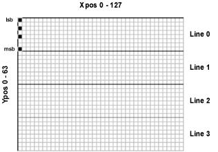
See also : LCDREAD,
PLOT, UNPLOT, see PRINT for LCD connections.
-----------------------------------------------------------------------------------------------------------------
5.37. LOOKDOWN
Syntax : Variable =
LOOKDOWN Index , [
Constant { , Constant…etc } ]
Overview
: Search
constants(s) for index value. If index matches one of the constants,
then store the matching constant’s position (0–N) in variable. If
no match is found, then the variable is unaffected.
Operators : Variable
is a user define variable that holds the result of the search.
Index
is the variable/constant being sought.
Constant(s),...
is a list of values. The target value is compared to these values
Example
: DIM Value
as BYTE
DIM Result as BYTE
Value = 177 ‘ The value to look for in the list
Result = 255 ‘ Default to value 255
Result = LOOKDOWN Value , [75,177,35,1,8,29,245]
PRINT "Value matches " , @Result , " in list"
In the above example, PRINT displays, “Value
matches 1 in list” because VALUE (177) matches item 1 of [75,177,35,1,8,29,245].
Note that index numbers count up from 0, not 1; that is in the list [75,177,35,1,8,29,245],
75 is item 0.
If the value is not in the list, then RESULT is
unchanged.
Notes : LOOKDOWN
is similar to the index of a book. You search for a topic and the index gives
you the page number. Lookdown searches for a value in a list, and stores the
item number of the first match in a variable.
LOOKDOWN also supports text phrases, which are basically lists of byte values, so they are also eligible for
Lookdown searches: -
DIM Value as BYTE
DIM Result as BYTE
Value = 101 ‘ ASCII “e”. the value to look for in the list
Result = 255 ‘ Default to value 255
Result = LOOKDOWN Value , ["Hello World"]
In the above example, RESULT will hold
a value of 1, which is the position of character ‘e’
See also : LOOKDOWNL,
LOOKUP, LOOKUPL
-----------------------------------------------------------------------------------------------------------------
5.38. LOOKDOWNL
Syntax : Variable =
LOOKDOWNL Index , {Operator} [ Value
{ , Value…etc } ]
Overview
: A
comparison is made between index and value; if the result is
true, 0 is written into variable. If that comparison was false, another
comparison is made between value and value1; if the result is
true, 1 is written into variable. This process continues until a true is
yielded, at which time the index is written into variable, or
until all entries are exhausted, in which case variable is unaffected.
Operators : Variable
is a user define variable that holds the result of the search.
Index
is the variable/constant being sought.
Value(s) can
be a mixture of 16-bit constants, string constants and variables. A
maximum of 50 values may be included in the list. Expressions may
not be used in the Value list, although they may be used as the index
value.
Operator
is an optional comparison operator and may be one of the
following: -
= equal
<> not equal
> greater than
< less than
>= greater than or equal to
<= less than or equal to
The optional operator can be used to perform a test
for other than equal to (“=”) while searching the list. For example, the list
could be searched for the first Value greater than the index parameter
by
using “>” as the operator. If operator
is left out, “=” is assumed.
Example
: Var
= LOOKDOWNL Wrd , [ 512 , Wrd1 , 1024 ]
Var = LOOKDOWNL Wrd
, < [ 10 , 100
, 1000 ]
Notes
: Because
LOOKDOWNL is more versatile than the standard LOOKDOWN
command, it generates larger code. Therefore, if the search list is made up
only of 8-bit constants and strings, use LOOKDOWN.
See also : LOOKDOWN,
LOOKUP, LOOKUPL
-----------------------------------------------------------------------------------------------------------------
5.39. LOOKUP
Syntax : Variable =
LOOKUP Index , [ Constant
{ , Constant…etc } ]
Overview
: Look
up the value specified by the index and store it in variable. If the index
exceeds the highest index value of the items in the list, then variable remains
unchanged.
Operators
: Variable
may be a constant, variable, or expression. This is where the retrieved value
will be stored.
Index
may be a constant of variable. This is the item number of the value to be
retrieved from the list.
Constant(s)
may be any 8-bit value (0-255). A maximum of 256 values may be included in the
list.
Example
: ‘ Create an animation of a spinning line.
DIM Index
as BYTE
DIM
Frame as BYTE
CLS ‘ Clear the LCD
Rotate: FOR Index = 0
TO 3 ‘ Create a loop of 4
Frame = LOOKUP Index , [ “|\-/” ] ‘ Table of animation characters
PRINT
AT 1 , 1 ,
Frame ‘ Display the character
DELAYMS
200 ‘ So we can see the animation
NEXT ‘ Close the loop
GOTO
Rotate ‘ Repeat forever
Notes
: index
starts at value 0. For example, in the LOOKUP command below. If the
first value (10) is required, then index will be loaded with 0, and 1 for the
second value (20) etc.
Var
= LOOKUP Index , [ 10 , 20 , 30 ]
See
also : LOOKUPL
-----------------------------------------------------------------------------------------------------------------
5.40. LOOKUPL
Syntax : Variable =
LOOKUPL Index , [ Value
{ , Value…etc } ]
Overview
: Look
up the value specified by the index and store it in variable. If the index
exceeds the highest index value of the items in the list, then variable remains
unchanged. Works exactly the same as LOOKUP, but allows variable types
or constants in the list of values.
Operators
: Variable
may be a constant, variable, or expression. This is where the retrieved value
will be stored.
Index
may be a constant of variable. This is the item number of the value to be
retrieved from the list.
Value(s) can
be a mixture of 16-bit constants, string constants and variables. A
maximum of 50 values may be included in the list.
Example : DIM
Var as BYTE
DIM
Wrd as WORD
DIM
Index as BYTE
DIM
Assign as WORD
Var
= 10
Wrd
= 1234
Index
= 0 ‘ Point to the first value in the list (WRD)
Assign= LOOKUPL
Index , [ Wrd , Var , 12345 ]
Notes
: Expressions
may not be used in the Value list, although they may be used as the Index
value.
Because LOOKUPL is capable of processing any
variable and constant type, the code produced is a lot larger than that of LOOKUP.
Therefore, if only 8-bit constants are required in the list, use LOOKUP
instead.
See
also : LOOKUP
-----------------------------------------------------------------------------------------------------------------
5.41. LOW (or CLEAR)
Syntax : LOW
(or CLEAR) Variable or Variable.Bit
Overview
: Place
a variable or bit in a low state. For a variable, this means filling it with
0’s. For a bit this means setting it to 0.
Operators : Variable can
be any variable or register, such as a Port
Variable.Bit can
be any variable and bit combination, i.e. PortA.1
Example : SYMBOL
LED = PORTB.4
LOW LED
CLEAR PORTB.3
LOW STATUS.0 ‘
Clear the carry flag
Notes : There
is no difference between the LOW and CLEAR commands.
If a port register is targeted using LOW,
then it is automatically set to output.
See also : DIM, HIGH, SYMBOL
|
|
|
|

The above diagram shows the connection of an LED to
any of the pins of a PIC. A resistor must be used in series with the LED to
limit the current supplied to it.
-----------------------------------------------------------------------------------------------------------------
5.42. ON_INTERRUPT
Syntax : ON_INTERRUPT
Label
Overview
: Jump
to a subroutine when a Hardware interrupt occurs
Operators : Label
is a valid identifier
Example
: ‘ Flash an LED attached to PortB.0 at a different rate to the
‘ LED attached to PortB.1
DEVICE 16F84
ON_INTERRUPT
Flash
‘ Assign some Interrupt associated aliases
SYMBOL T0IE INTCON.5 ' TMR0 Overflow Interrupt Enable
SYMBOL T0IF INTCON.2 ' TMR0 Overflow Interrupt Flag
SYMBOL GIE INTCON.7 '
Global Interrupt Enable
SYMBOL PS0 OPTION_REG.0 ' Prescaler ratio bit-0
SYMBOL PS1 OPTION_REG.1 ' Prescaler ratio bit-1
SYMBOL PS2 OPTION_REG.2 ' Prescaler ratio bit-2
' Prescaler
Assignment (1=assigned to WDT 0=assigned to oscillator)
SYMBOL PSA
OPTION_REG.3
' Timer0 Clock
Source Select (0=Internal clock 1=External PORTA.4)
SYMBOL T0CS
OPTION_REG.5
SYMBOL LED PORTB.1
GOTO
Over_interrupt ‘ Jump over the interrupt subroutine
‘ Interrupt routine starts here
Flash: CONTEXT
SAVE ‘ Save the
registers
'
XOR PortB with 1, Which will turn on with one interrupt
' and turn off
with the next the LED connected to PortB.0
PORTB = PORTB ^ 1
T0IF = 0 ' Clear the TMR0 overflow flag
CONTEXT RESTORE ‘ Restore the
registers and exit
Over_interrupt
: TRISB
= %00000000 ' Configure PortB as outputs
PORTB = 0 ‘ Clear PortB
‘ Initiate the interrupt
GIE = 0 ' Turn off global interrupts
PSA = 0 ' Assign the prescaler to external oscillator
PS0 = 1 ' Set the prescaler
PS1 = 1 ' to increment TMR0
PS2 = 1 ' every 256th instruction cycle
T0CS = 0 ' Assign TMR0 clock to internal source
TMR0 = 0 ' Clear TMR0 initially
T0IE = 1 ' Enable TMR0 overflow interrupt
GIE = 1 ' Enable global interrupts
Inf: LOW
LED
DELAYMS 500
HIGH
LED
DELAYMS
500
GOTO Inf
Initiating
an interrupt.
Before
we can change any bits that correspond to interrupts we need to make sure that
global interrupts are disabled. This is done by clearing the GIE bit of INTCON
(INTCON.7). Sometimes an interrupt may occur while the GIE bit is being
cleared, which means that the bit is not actually cleared and global interrupts
are not disabled. To make sure that the GIE bit is actually cleared we must
poll it. This can be accomplished by a simple loop: -
GIE = 0 ‘ Disable global interrupts
WHILE
GIE = 1 ‘ Make sure they are off
GIE = 0 ‘ Continue to clear GIE
WEND ‘ Exit when GIE is clear
The
prescaler attachment to TMR0 is controlled by bits 0:2 of the OPTION_REG (PS0,
1, 2). The table below shows their relationship to the prescaled ratio
applied. But before the prescaler can be calculated we must inform the PIC as
to what clock governs TMR0. This is done by setting or clearing the PSA bit of
OPTION_REG (OPTION_REG.3). If PSA is cleared then TMR0 is attached to
the external crystal oscillator. If it is set then it is attached to the
watchdog timer, which uses the internal RC oscillator. This is important to
remember; as the prescale ratio differs according to which oscillator it is
attached to.
|
PS2 |
PS1 |
PS0 |
PSA=0
(External crystal OSC) |
PSA=1
(Internal WDT OSC) |
|
0 |
0 |
0 |
1
: 2 |
1
: 1 |
|
0 |
0 |
1 |
1
: 4 |
1
: 2 |
|
0 |
1 |
0 |
1
: 8 |
1
: 4 |
|
0 |
1 |
1 |
1
: 16 |
1
: 8 |
|
1 |
0 |
0 |
1
: 32 |
1
: 16 |
|
1 |
0 |
1 |
1
: 64 |
1
: 32 |
|
1 |
1 |
0 |
1
: 128 |
1
: 64 |
|
1 |
1 |
1 |
1
: 256 |
1
: 128 |
TMR0
prescaler ratio configurations.
As
can be seen from the above table, if we require TMR0 to increment on every
instruction cycle (4/OSC) we must clear PS2..0 and set PSA, which would
attach it to the watchdog timer. This will cause an interrupt to occur every
256us (assuming a 4MHz crystal). If the same values were placed into
PS2..0 and PSA was cleared (attached to the external oscillator) then
TMR0 would increment on every 2nd instruction cycle and cause an
interrupt to occur every 512us.
There is however, another way
TMR0 may be incremented. By setting the T0CS bit of the OPTION_REG (OPTION_REG.5)
a rising or falling transition on PortA.0 will also increment TMR0. Setting
T0CS will attach TMR0 to PortA.0 and clearing TOCS will attach it to the
oscillators. If PortA.0 is chosen then an associated bit, T0SE (OPTION_REG.4)
must be set or cleared. Clearing T0SE will increment TMR0 with a low to high
transition, while setting T0SE will increment TMR0 with a high to low
transition.
The
prescaler’s ratio is still valid when PortA.0 is chosen as the source, so that
every nth transition on
PortA.0 will increment TMR0. Where n is the prescaler ratio.
Before the
interrupt is enabled, TMR0 itself should be assigned a value, as any variable
should be when first starting a program. In most cases clearing TMR0 will
suffice. This is necessary because, when the PIC is first powered up the value
of TMR0 could be anything from 0 to 255
We are now
ready to allow TMR0 to trigger an interrupt. This is accomplished by setting
the T0IE bit of INTCON (INTCON.5). Setting this bit will not cause a
global interrupt to occur just yet, but will inform the PIC that when global
interrupts are enabled, TMR0 will be one possible cause. When TMR0 overflows (rolls
over from 255 to 0) the T0IF (INTCON.2) flag is set. This is not
important yet but will become crucial in the interrupt handler subroutine.
The final
act is to enable global interrupts by setting the GIE bit of the INTCON
register (INTCON.7).
Format of the interrupt
handler.
The interrupt handler
subroutine must always follow a fixed pattern. First, the contents of the
STATUS, PCLATH, FSR, and Working register must be saved, this is termed context
saving. A command has been added that does this automatically named CONTEXT
SAVE. Variable space is automatically allocated for the registers.
When the interrupt handler
was called the GIE bit was automatically cleared by hardware, disabling any
more interrupts. If this were not the case, another interrupt might occur while
the interrupt handler was processing the first one, which would lead to
disaster.
Now the T0IF (TMR0
overflow) flag becomes important. Because, before exiting the interrupt
handler it must be cleared to signal that we have finished with the interrupt
and are ready for another one.
T0IF = 0 ' Clear the TMR0 overflow flag
Also the STATUS, PCLATH, FSR, and
Working register must
be returned to their original conditions (context restoring). Again, the
CONTEXT command may be used, but this time with RESTORE after it.
i.e. CONTEXT RESTORE.
The CONTEXT RESTORE
command also returns the PIC back to the main body code where the interrupt was
called from.
Precautions.
Note that the code between
the context saving and restoring does not necessarily need to be in assembler,
a small subset of BASIC commands SHOULD work just as well, but care must be
used as to the commands that are placed within the interrupt handler itself, as
most commands are non re-entrant. I2CBUS, SERIAL, and LCD routines
etc, should be avoided, as they use system variables that may be already in use
in the main body code.
Also, DELAY commands should be avoided at all costs, as these place the PIC into a timed loop, thus, altering any interrupt timing.
IF-THEN, REPEAT-UNTIL, and WHILE-WEND comparisons should be safe, along with register or variable altering commands.
LOOKUP and LOOKDOWN are permitted, but not LOOKUPL or LOOKDOWNL.
Because a hardware interrupt may occur at any time, I cannot fully guarantee that a SYSTEM variable will not be disturbed while inside the interrupt handler, therefore, the safest way to use an interrupt is to write the code in assembler. This will guarantee that no system variables are being altered. Alternatively, the assembler code may be viewed in order to ascertain whether any system variables are being used. These are: -
PP0,
PP0H, PP1, PP1H, PP2, PP2H, PP3, PP3H, PP4, PP4H, PP5, PP5H, PP6, PP6H, PP7,
PP7H, GEN, GENH, GEN2, GEN2H, GEN4, GEN4H, GPR, BPF.
The code within the interrupt handler should be as quick and efficient as possible because, while it’s processing the code the main program is halted.
When using assembler
interrupts, care should be taken to ensure that the watchdog timer does not time-out.
Placing a CLRWDT instruction at regular intervals within the code will
prevent this from happening. An alternative approach would be to disable the
watchdog timer altogether at programming time.
The following example illustrates the use of a TMR0
interrupt as a crude clock: -
' LCD clock program using ON_INTERRUPT
' Uses TMR0 and prescaler.
' Nap and Sleep should not be used.
' Buttons may be used to set Hours and
Minutes
REMARKS on
DEVICE 16F628
On_Interrupt Goto
Clockint
DIM Hour as BYTE ' Hour variable
DIM Dhour as BYTE ' Display Hour variable
DIM Minute as BYTE ' Minute variable
DIM Second as BYTE ' Second variable
DIM Ticks as BYTE ' Pieces of Seconds variable
Dim Update as BYTE '
Variable to indicate Update of LCD
CMCON = 7 ' PORTA to digital (for 16F62X devices)
CLS ' Clear the LCD
Hour=0:Minute=0:Second=0:Ticks=0 ' Set initial time to
00:00:00
Update = 1 ' Force first display
' Set TMR0 to interrupt every 16.384
milliseconds (ms)
OPTION_REG =
%01010101
' Set
TMR0 configuration
INTCON = %10100000
'
Enable TMR0 interrupts
' ** Main program loop Updates the LCD
with the time **
Main: PORTA = 0 ' PORTA lines low to read buttons
TRISA = %00001111 '
Enable all button pins as inputs
' Check any button pressed to set time
IF PORTA.3 = 0 THEN
Dec_Min
IF PORTA.2 = 0 THEN
Inc_Min ' Last 2 buttons set Minute
IF PORTA.1 = 0 THEN
Dec_Hour
IF PORTA.0 = 0 THEN Inc_Hour ' First 2
buttons set Hour
C_Upd: IF
Update = 1 THEN ' Check for
time to Update screen
' Display time as hh:mm:ss
Dhour = Hour
' Change Hour 0 to 12
IF (Hour // 12) = 0 THEN
Dhour = Dhour + 12
CURSOR 1 , 3
IF Hour < 12 THEN ' Check for AM or PM
PRINT DEC2 DHour, ":", DEC2 Minute, ":", DEC2 Second, " AM"
ELSE
PRINT DEC2 (DHour-12), ":", DEC2 Minute, ":", DEC2 Second, " PM"
ENDIF
Update = 0 ' Clear Screen Update
ENDIF
GOTO Main ' Do it forever
Inc_Min: ' Increment Minutes
Minute = Minute + 1
IF Minute >= 60 THEN Minute = 0
GOTO Debounce
Inc_Hour: ' Increment Hours
Hour = Hour + 1
IF Hour >= 24 THEN Hour = 0
GOTO Debounce
Dec_Min: ' Decrement Minutes
Minute = Minute - 1
IF Minute >= 60 THEN Minute = 59
GOTO Debounce
Dec_Hour: ' Decrement Hours
Hour = Hour - 1
IF Hour >= 24 THEN Hour = 23
Debounce: ' Debounce and delay for 250ms
DELAYMS 250
Update = 1 ' Set to Update screen
GOTO C_Upd
' ** Interrupt routine to handle each
timer tick **
Clockint:
CONTEXT SAVE
Ticks = Ticks + 1 ' Count the pieces of Seconds
IF Ticks < 61 THEN Texit ' 61 Ticks per Second (16.384ms per
tick)
' One Second elapsed so Update time
Ticks = 0
Second = Second + 1
IF Second >= 60 THEN
Second =
0
Minute =
Minute + 1
IF
Minute >= 60 THEN
Minute = 0
Hour
= Hour + 1
IF
Hour >= 24 THEN Hour = 0
ENDIF
ENDIF
Update = 1 ' Set to Update LCD
Texit: INTCON.2 = 0 ' Reset timer interrupt flag
Context Restore
-----------------------------------------------------------------------------------------------------------------
5.43. OUTPUT
Syntax : OUTPUT Port . Pin
Overview
: Makes the specified Pin an output.
Operators
: Port.Pin must
be a Port.Pin constant declaration.
Example
: OUTPUT PortA.0 ‘ Make bit-0 of PortA
an output
Notes : An Alternative method for making a particular
pin an output is by directly modifying the TRIS: -
TRISB.0 = 0 ‘ Set PORTB, bit-0 to an output
The above method is
quicker, and produces less code than the OUTPUT command.
All of the pins on a
port may be set to output by setting the whole TRIS register at once: -
TRISB = %00000000 ‘ Set all of
PORTB to outputs
In the above
examples, setting a TRIS bit to 0 makes the pin an output, and conversely,
setting the bit to 1 makes the pin an input.
-----------------------------------------------------------------------------------------------------------------
5.44. ORG
Syntax : ORG Value
Overview
: Set the program origin for subsequent code at the
address defined in
Value
Operators
: Value can be any constant value
within the range of the particular PICmicro’s memory.
Example
: DEVICE 16F877
ORG
2000 ‘ Set the origin to address 2000
CDATA
120 , 243 , ”Hello” ‘ Place data starting at address 2000
or
SYMBOL Address = 2000
ORG
Address + 1 ‘ Set the origin to address 2001
CDATA
120 , 243 , ”Hello” ‘ Place data starting at address 2001
Notes : If more complex values are
required after the ORG directive, such as assembler variables etc. Use :
-
@ ORG { assembler variables etc }
See CDATA for an alternative method for
locating the address of a CDATA table.
-----------------------------------------------------------------------------------------------------------------
5.45. PEEK
Syntax : Variable = PEEK Address
Overview
: Retrieve
the value of a register and place into a variable
Operators : Variable is
a user defined variable.
Address can
be a constant or a variable, pointing to the address of a register.
Example 1 : A
= PEEK 15
Variable A will contain the value of Register 15.
If the device is a 16F84, for example, this register is one of the 68 general-purpose
registers (RAM).
Example 2 : B
= 15
A = PEEK B
Same function as example
1
Notes
: Use of the PEEK
command is not recommended. A more efficient way of retrieving the value from a
register is by accessing the register directly: -
VARIABLE
= REGISTER
See also : POKE
-----------------------------------------------------------------------------------------------------------------
5.46. PIXEL (NOT AVAILABLE IN THE LITE VERSION)
Syntax : Variable = PIXEL Ypos
, Xpos
Overview
: Read
the condition of an individual pixel on a 64x128 element graphic LCD. The
returned value will be 1 if the pixel is set, and 0 if the pixel is clear.
Operators : Variable is
a user defined variable.
Xpos can
be a constant, variable, or expression, pointing to the X-axis location of the
pixel to examine. This must be a value of 0 to 127. Where 0 is the far left row
of pixels.
Ypos can
be a constant, variable, or expression, pointing to the Y-axis location of the
pixel to examine. This must be a value of 0 to 63. Where 0 is the top column of
pixels.
Example : DEVICE 16F877
Declare LCD_TYPE
GRAPHIC ' Use a Graphic LCD
Declare INTERNAL_FONT
OFF ‘
Use an external chr set
Declare FONT_ADDR 0 ‘
Eeprom’s address is 0
' Graphic LCD Pin Assignments
DECLARE LCD_DTPORT PORTD
DECLARE
LCD_RSPIN PORTC.2
DECLARE
LCD_RWPIN PORTE.0
DECLARE
LCD_ENPIN PORTC.5
DECLARE
LCD_CS1PIN PORTE.1
DECLARE
LCD_CS2PIN PORTE.2
' Character set eeprom Pin Assignments
Declare SDA_PIN PORTC.4
Declare SCL_PIN PORTC.3
DIM
Xpos as BYTE
DIM
Ypos as BYTE
DIM
Result as BYTE
CLS
PRINT
AT 0 , 0
, “TESTING
1-2-3”
‘ Read the top
row and display the result
FOR
Xpos = 0 TO 127
Result
= PIXEL 0 , Xpos ‘ Read the top row
PRINT
AT 1 , 0 ,
@Result
DELAYMS
400
NEXT
STOP
See also : LCDREAD,
LCDWRITE, PLOT, UNPLOT. See PRINT for circuit.
-----------------------------------------------------------------------------------------------------------------
5.47. PLOT (NOT AVAILABLE IN THE LITE VERSION)
Syntax : PLOT
Ypos , Xpos
Overview : Set
an individual pixel on a 64x128 element graphic LCD.
Operators
: Xpos can
be a constant, variable, or expression, pointing to the X-axis location of the
pixel to set. This must be a value of 0 to 127. Where 0 is the far left row of
pixels.
Ypos can
be a constant, variable, or expression, pointing to the Y-axis location of the
pixel to set. This must be a value of 0 to 63. Where 0 is the top column of
pixels.
Example : DEVICE 16F877
Declare LCD_TYPE
GRAPHIC ' Use a Graphic LCD
' Graphic LCD Pin Assignments
DECLARE LCD_DTPORT PORTD
DECLARE
LCD_RSPIN PORTC.2
DECLARE
LCD_RWPIN PORTE.0
DECLARE
LCD_ENPIN PORTC.5
DECLARE
LCD_CS1PIN PORTE.1
DECLARE
LCD_CS2PIN PORTE.2
DIM
Xpos as BYTE
ADCON1 = 7 ‘ Set PORTA and PORTE to all digital
‘
Draw a line across the LCD
Again: FOR
Xpos = 0 TO 127
PLOT 20 , Xpos
DELAYMS 10
NEXT
‘ Now erase the line
FOR
Xpos = 0 TO 127
UNPLOT 20 , Xpos
DELAYMS 10
NEXT
GOTO
Again
See also : LCDREAD,
LCDWRITE, PIXEL, UNPLOT. See PRINT for circuit.
|
|
|
|
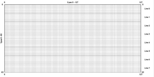
Graphic LCD pixel
configuration.
-----------------------------------------------------------------------------------------------------------------
5.48. POKE
Syntax : POKE
Address ,
Variable
Overview : Assign
a value to a register.
Operators
: Address can
be a constant or a variable, pointing to the address of a register.
Variable can
be a constant or a variable.
Example : A
= 15
POKE 12 , A ‘ Register 12 will be assigned the value 15.
POKE A
, 0 ‘ Register 15 will be assigned the value 0
Notes
: Use of the POKE
command is not recommended. A more efficient way of assigning a value to a
register is by accessing the register directly: -
REGISTER
= VALUE
See also : PEEK
-----------------------------------------------------------------------------------------------------------------
5.49. POT
Syntax : Variable =
POT Pin , Scale
Overview
: Read a potentiometer, thermistor, photocell, or other variable
resistance.
Operators
: Variable is a user defined variable.
Pin is a Port.Pin constant that specifies the I/O pin to use.
Scale is a constant, variable, or expression, used to scale the instruction’s internal 16-bit result. The 16-
bit reading is multiplied by (scale/ 256), so a scale value of 128 would
reduce the range by approximately 50%, a scale of 64 would reduce to 25%, and
so on.
Example : DIM Var as BYTE
Loop: Var
= POT PORTB.0 , 100 ' Read
potentiometer on pin 0 of PortB.
PRINT @Var , “ ” ' Display the potentiometer reading
GOTO
Loop ' Repeat the
process.
Notes
: Internally, the POT instruction calculates a 16-bit value,
which is scaled down to an 8-bit value. The amount by which the internal value
must be scaled varies with the size of the resistor being used.
1
The pin specified by POT must be
connected to one side of a resistor, whose other side is connected through a
capacitor to ground. A resistance measurement is taken by timing how long it takes
to discharge the capacitor through the resistor.
|
|
|
|
The value of scale must be
determined by experimentation, however, this is easily accomplished as follows:
-
Set the device under measure, the pot
in this instance, to maximum resistance and read it with scale set to
255. The value returned in Var can now be used as scale: -
Var = POT PORTB.0 , 255
See also : ADIN, RCIN
-----------------------------------------------------------------------------------------------------------------
5.50. PRINT
Syntax : PRINT
Item { , Item... }
Overview
: Send
Text to an LCD module using the Hitachi 44780 controller or a graphic LCD based
on the Samsung S6B0108 chipset.
Operators
: Item
may be a constant, variable, expression, modifier, or string list.
There are no operators as such, instead there are modifiers.
For example, if an at sign ‘@’ precedes an Item, the ASCII
representation for each digit is sent to the LCD.
The modifiers
are listed below: -
Modifier Operation
AT ypos (1 to n),xpos(1 to n) Position
the cursor on the LCD
BIN{1..16} Send
binary digits
CLS Clear the LCD (also creates a
30ms delay)
DEC{1..5} Send
decimal digits
HEX{1..4} Send
hexadecimal digits
REP c\n Send
character c repeated n times
The numbers after the BIN, DEC, and HEX modifiers
are optional. If they are omitted, then the default is all the digits that make
up the value will be displayed.
The Xpos and Ypos values in the AT modifier
both start at 1. For example, to place the text “HELLO WORLD” on line 1,
position 1, the code would be: -
PRINT AT 1 , 1 , “HELLO WORLD”
Example : DIM
Var as BYTE
DIM
Wrd as WORD
PRINT
“Hello World” ‘ Display the text “Hello World”
PRINT
“Var= “ , DEC Var ‘ Display the decimal value of VAR
PRINT
“Var= “ , HEX Var ‘ Display the hexadecimal value of VAR
PRINT
“Var= “ , BIN Var ‘ Display the binary value of VAR
PRINT
“Var= “ , @Var ‘ Display the decimal value of VAR
Declares : There
are six DECLARES for use with an alphanumeric LCD and PRINT: -
DECLARE LCD_TYPE 1 or 0 , GRAPHIC
or ALPHA
Inform the compiler as to the type of LCD that the PRINT
command will output to. If GRAPHIC or 1 is chosen then any output by the PRINT
command will be directed to a graphic LCD based on the
Samsung S6B0108 chipset. A value of 0 or ALPHA, or if the DECLARE is not
issued will target the standard alphanumeric LCD type
Targeting the graphic LCD will also enable commands
such as PLOT, UNPLOT, LCDGET, and LCDPUT.
DECLARE LCD_DTPIN PORT . PIN
Assigns the Port and Pins that the LCD’s DT (data)
lines will attach to.
The LCD may be connected to the PICmicro using
either a 4-bit bus or an 8-bit bus. If an 8-bit bus is used, all 8 bits must be
on one port. If a 4-bit bus is used, it must be connected to either the bottom
4 or top 4 bits of one port. For example: -
DECLARE LCD_DTPIN PORTB.4 ‘ Used for
4-line interface.
DECLARE LCD_DTPIN PORTB.0 ‘ Used for 8-line interface.
In the examples above, PortB is only a personal
preference. The LCD’s DT lines may be attached to any valid port on the PIC. If
the DECLARE is not used in the program, then the default Port and Pin is
PortB.4, which assumes a 4-line interface.
.
DECLARE
LCD_ENPIN PORT . PIN
Assigns
the Port and Pin that the LCD’s EN line will attach to.
If the DECLARE is not used in the program, then the
default Port and Pin is PortB.2.
DECLARE
LCD_RSPIN PORT . PIN
Assigns
the Port and Pins that the LCD’s RS line will attach to.
If the DECLARE is not used in the program, then the
default Port and Pin is PortB.3.
DECLARE
LCD_INTERFACE 4 or 8
Inform the compiler as to whether a 4-line or
8-line interface is required by the LCD.
If the DECLARE is not used in the program, then the
default interface is a 4-line type.
DECLARE
LCD_LINES 1 , 2 , or 4
Inform
the compiler as to how many lines the LCD has.
LCD’s come in a range of sizes, the most popular
being the 2 line by 16 character types. However, there are 4-line types as
well. Simply place the number of lines that the particular LCD has, into the
declare.
If the DECLARE is not used in the program, then the
default number of lines is 2.
Notes
: If
no modifier precedes an item in a PRINT command, then the characters
value is sent to the LCD. This is useful for sending control codes to the LCD.
For example: -
PRINT $FE , 128
Will move the
cursor to line 1, position 1 (HOME).
Below is a list
of useful control commands: -
Control Command Operation
$FE, 1 Clear
display
$FE, 2 Return
home (beginning of first line)
$FE, $0C Cursor
off
$FE, $0E Underline
cursor on
$FE, $0F Blinking
cursor on
$FE, $10 Move
cursor left one position
$FE, $14 Move
cursor right one position
$FE, $C0 Move
cursor to beginning of second line
$FE, $94 Move
cursor to beginning of third line
$FE, $D4 Move
cursor to beginning of fourth line
Note that if the command for clearing the LCD is
used, then a small delay should follow it: -
PRINT $FE
, 1 : DELAYMS 30
|
|
|
|
The above diagram shows
the default connections for an alphanumeric LCD module. In this instance,
connected to the 16F84 PICmicro.
Using a Graphic LCD (NOT AVAILABLE
IN THE LITE VERSION)
Once a graphic LCD has been chosen using the DECLARE
LCD_TYPE directive, all PRINT outputs will be directed to that
LCD.
The standard modifiers may also be used with the
graphics LCD: -
AT ypos (0 to 7),xpos (0 to 20)
Position the cursor on the LCD
BIN{1..16} Send
binary digits
CLS Clear the LCD
DEC{1..5} Send
decimal digits
HEX{1..4} Send
hexadecimal digits
REP c\n Send
character c repeated n times
Most of the above modifiers still work in the
expected manner, however, the AT modifier now starts at Ypos 0 and Xpos
0, where values 0,0 will be the top left corner of the LCD.
There are also four new modifiers. These are: -
FONT 0 to n Choose
the nth font, if available
INVERSE 0-1 Invert
the characters sent to the LCD
OR 0-1 OR
the new character with the original
XOR 0-1 XOR
the new character with the original
Once one of the four new modifiers has been
enabled, all future PRINT commands will use that particular feature
until the modifier is disabled. For example: -
‘ Enable inverted characters from this
point
PRINT AT 0 , 0 , INVERSE 1 , “HELLO WORLD”
PRINT AT 1 ,
0 , “STILL INVERTED”
‘ Now use normal characters
PRINT AT 2 , 0 , INVERSE 0 , “NORMAL CHARACTERS”
If no modifiers are present, then the character’s
ASCII representation will be displayed: -
‘ Print characters A and B
PRINT AT 0 , 0 , 65 , 66
Declares : There
are six declares associated with a graphic LCD.
DECLARE LCD_DTPORT PORT
Assign the port
that will output the 8-bit data to the graphic LCD.
If the DECLARE
is not used, then the default port is PORTD.
DECLARE LCD_RWPIN PORT . PIN
Assigns the Port and Pin that the graphic LCD’s RW
line will attach to.
If
the DECLARE is not used in the program, then the default Port and Pin is
PortE.0.
DECLARE LCD_CS1PIN
PORT . PIN
Assigns the Port and Pin that the graphic LCD’s CS1
line will attach to.
If
the DECLARE is not used in the program, then the default Port and Pin is
PortC.0.
DECLARE LCD_CS2PIN
PORT . PIN
Assigns the Port and Pin that the graphic LCD’s CS2
line will attach to.
If
the DECLARE is not used in the program, then the default Port and Pin is
PortC.2.
Note : Along
with the new declares, two of the existing LCD declares must also be used.
Namely, RS_PIN and EN_PIN.
DECLARE INTERNAL_FONT ON - OFF, 1 or 0
The graphic LCDs that are
compatible with PICBASIC PLUS are non-intelligent types, therefore, a separate
character set is required. This may be in one of two places, either externally,
in an I2C eeprom, or internally in a CDATA table.
If the DECLARE is omitted
from the program, then an external font is the default setting.
If an external font is
chosen, the I2C eeprom must be connected to the specified SDA and
SCL pins (as dictated by DECLARE SDA and DECLARE SCL).
If an internal font is
chosen, it must be on a PIC device that has self modifying code features, such
as the 16F87X range.
The CDATA table that
contains the font must have a label, named FONT: preceding it. For example: -
FONT:- { data for characters 0 to 64 }
CDATA $7E ,
$11 , $11 , $11 , $7E , $0 ‘ Chr 65 “A”
CDATA $7F , $49 , $49 , $49 , $36 , $0 ‘ Chr 66 “B”
{ rest of font
table }
Notice the dash after the
font’s label, this disables any bank switching code that may otherwise disturb
the location in memory of the CDATA table.
The font table may be
anywhere in memory, however, it is best placed after the main program code.
The font is built up of an
8x6 cell, with only 5 of the 6 rows, and 7 of the 8 columns being used for
alphanumeric characters. See the
diagram below.
|
|
|
|
However, if a graphic
character is chosen (chr 0 to 31), the whole of the 8x6 cell is used. In this
way, large fonts and graphics may be easily constructed.
|
|
|
|
A list of the graphic
characters is shown at the end of the PRINT description.
The character set itself is
128 characters long (0 -127). Which means that all the ASCII characters are
present, including $, %, &, # etc.
There are two programs on the
compiler’s CDROM, that are for use with internal and external fonts. INT_FONT.BAS,
contains a CDATA table that may be cut and pasted into your own program
if an internal font is chosen. EXT_FONT.BAS, writes the character set to
a 24C32 I2C eeprom for use with an external font. Both programs are
fully commented.
DECLARE FONT_ADDR 0 to 7
Set the slave
address for the I2C eeprom that contains the font.
When an external source for
the font is used, it may be on any one of 8 eeproms attached to the I2C
bus. So as not to interfere with any other eeproms attached, the slave address
of the eeprom carrying the font code may be chosen.
If
the DECLARE is omitted from the program, then address 0 is the default slave
address of the font eeprom.
Important
: Because
of the complexity involved with interfacing to the graphic LCD, five of
the eight stack levels available are used when the PRINT command is
issued with an external font. Therefore, be aware that if PRINT is used
within a subroutine, you must limit the amount of subroutine nesting
that may take place.
If an internal
font is implemented, then only four stack levels are used.
If the default
setting of PORTE is used for the LCD’s CS1, CS2, and RW pin connections, then
these pins should be set to digital by issuing the following line of code near
the beginning of the program: -
ADCON1 = 7 ‘ Set PORTA and PORTE to all digital
You will need to
refer to the PIC’s datasheet for ADCON1 settings if PORTA is to be used for
analogue inputs.
|
|
|
|
The above diagram shows the connections required
for an external font.
The eeprom has a slave address of 0. If an internal
font is used, then the eeprom may be omitted.
The below diagram lists the graphic characters
available. For example, to display a single horizontal bar, the BASIC code
would be: -
PRINT AT
0 , 0 , 8 , 8 , 8 , 8 , 8 , 8 , 8 , 8 , 8 , 8 , 8
Any of the character set may be altered to suit
your personal needs, however, characters 26 to 31 are left blank to be used for
user defined characters.
|
|
|
|
-----------------------------------------------------------------------------------------------------------------
5.51. PULSIN
Syntax : Variable
= PULSIN Pin , State
Overview : Change the specified pin to input and measure an input pulse.
Operators
: Variable is a user defined variable.
This may be a word variable with a range of 1 to 65535, or a byte variable with
a range of 1 to 255.
Pin is a Port.Pin constant that specifies the I/O pin to use.
State is a constant (0 or 1) or name HIGH - LOW that specifies which
edge must occur before beginning the measurement.
Example : DIM Var as BYTE
Loop: Var
= PULSIN PORTB.0 , 100 , 1 ’ Measure a pulse on pin 0
of PortB.
PRINT @Var , “ ” ' Display the reading
GOTO Loop ' Repeat the
process.
Notes
: PULSIN
acts as a fast clock that is triggered by a change in state (0 or 1) on the
specified pin. When the state on the pin changes to the state specified, the
clock starts counting. When the state on the pin changes again, the clock
stops. If the state of the pin doesn’t change (even if it is already in the
state specified in the PULSIN instruction), the clock won’t trigger. PULSIN
waits a maximum of 0.65535 seconds for a trigger, then returns with 0 in variable.
The variable can be either a WORD or a
BYTE. If the variable is a word, the value returned by PULSIN can range
from 1 to 65535 units.
The units are dependant on the
frequency of the crystal used. If a 4MHz crystal is used, then each unit is
10us, while a 20MHz crystal produces a unit length of 2us.
If the variable is a byte and the
crystal is 4MHz, the value returned can range from 1 to 255 units of 10µs.
Internally, PULSIN always uses a 16-bit timer. When your program
specifies a byte, PULSIN stores the lower 8 bits of the internal counter
into it. Pulse widths longer than 2550µs will give false, low readings with a
byte variable. For example, a 2560µs pulse returns a reading of 256 with a word
variable and 0 with a byte variable.
See also : COUNTER, PULSOUT
-----------------------------------------------------------------------------------------------------------------1
5.52. PULSOUT
Syntax : PULSOUT
Pin , Period, {
Initial State }
Overview
: Generate
a pulse on Pin of specified Period. The pulse is generated by
toggling the pin twice, thus the initial state of the pin determines the
polarity of the pulse. Or alternatively, the initial state may be set by using
HIGH-LOW or 1-0 after the Period. Pin is automatically made an
output.
Operators : Pin is a Port.Pin constant that
specifies the I/O pin to use.
Period
can be a constant of user defined variable. See notes.
State is an optional constant (0 or 1) or name HIGH - LOW that
specifies the state of the outgoing pulse.
Example
: ‘ Send a high pulse 1ms long (at 4MHz) to PortB Pin5
LOW PORTB.5
PULSOUT PORTB.5 ,
100
‘ Send a high pulse 1ms long (at 4MHz) to PortB Pin5
PULSOUT PORTB.5 ,
100 , HIGH
Notes
: The
resolution of PULSOUT is dependent upon the oscillator frequency. If a
4MHz oscillator is used, the Period of the generated pulse will be in
10us increments. If a 20MHz oscillator is used, Period will have a 2us
resolution. Declaring an XTAL value has no effect on PULSOUT. The
resolution always changes with the actual oscillator speed.
See also : COUNTER , PULSIN
-----------------------------------------------------------------------------------------------------------------
5.53. PWM
Syntax : PWM
Pin , Duty , Cycles
Overview
: Output
pulse-width-modulation on a pin, then return the pin to input state.
Operators : Pin is a Port.Pin constant that
specifies the I/O pin to use.
Duty is
a variable, constant (0–255), or expression, which specifies the analogue level
desired (0–5 volts).
Cycles is
a variable or constant (0–255) which specifies the number of cycles to output.
Larger capacitors require multiple cycles to fully charge. Cycle time is
dependant on Xtal frequency. If a 4MHz crystal is used, then cycle takes
approx 5 ms. If a 20MHz crystal is used, then cycle takes approx 1 ms.
Notes
: PWM
can be used to generate analogue voltages (0-5V) through a pin connected to a
resistor and capacitor to ground; the resistor-capacitor junction is the
analogue output (see circuit). Since the capacitor gradually discharges, PWM
should be executed periodically to refresh the analogue voltage.
|
|
|
|
PWM emits a burst of 1s and
0s whose ratio is proportional to the duty value specified. If duty is
0, then the pin is continuously low (0); if duty is 255, then the pin is
continuously high. For values in between, the proportion is duty/255. For
example, if duty is 100, the ratio of 1s to 0s is 100/255 = 0.392,
approximately 39 percent.
When such a burst is used to charge a capacitor
arranged, the voltage across the capacitor is equal to:-
(duty/ 255) * 5.
So if duty is 100, the capacitor voltage is
(100/255) * 5 = 1.96 volts.
This voltage will drop as the capacitor discharges
through whatever load it is driving. The rate of discharge is proportional to
the current drawn by the load; more current = faster discharge. You can reduce
this effect in software by refreshing the capacitor’s charge with frequent use
of the PWM command. You can also buffer the output using an op-amp to
greatly reduce the need for frequent PWM cycles.
-----------------------------------------------------------------------------------------------------------------
5.54. RANDOM
Syntax : Variable =
RANDOM
Overview
: Generate
a pseudo-randomisation on Variable. Variable should be a 16-bit
variable.
Operators
: Variable is
used both as the seed and to store the result. The pseudo-random algorithm used
has a working length of 1 to 65535 (only zero is not produced).
Example : Var
= RANDOM ‘ Get a random number into Var
-----------------------------------------------------------------------------------------------------------------
5.55. RCIN
Syntax : Variable =
RCIN Pin , State
Overview
: Count
time while pin remains in state, usually used to measure the charge /
discharge time of resistor / capacitor (RC) circuit.
Operators
: Pin is a Port.Pin constant that
specifies the I/O pin to use. This pin will be placed into input mode and
left in that state when the instruction finishes.
State is
a variable or constant (1 or 0) that will end the Rcin period. Text, HIGH or
LOW may also be used instead of 1 or 0.
Variable is
a variable in which the time measurement will be stored.
Notes
: The
resolution of RCIN is dependent upon the oscillator frequency. If a 4MHz
oscillator is used, the time in state is returned in 10us increments. If a
20MHz oscillator is used, the time in state will have a 2us resolution.
Declaring an XTAL value has no effect on RCIN. The resolution always
changes with the actual oscillator speed. If the pin never changes state 0 is returned.
RCIN can be used to measure
the charge or discharge time of a resistor/capacitor circuit. This allows
measurement of resistance or capacitance, use R or C sensors such as
thermistors or capacitive humidity sensors or respond to user input through a
potentiometer. In a broader sense, RCIN can also serve as a fast,
precise stopwatch for events of very short duration.
When RCIN executes, it starts a counter. The
counter stops as soon as the specified pin is no longer in State (0 or
1). If pin is not in State when the instruction executes, RCIN
will return 1 in Variable, since the instruction requires one timing
cycle to discover this fact. If pin remains in State longer than 65535
timing cycles RCIN returns 0.
|
|
|
|
|
Figure A |
|
Figure B |
The diagrams above show two suitable RC circuits
for use with RCIN. The circuit in figure B is preferred, because the
PIC’s logic threshold is approximately 1.5 volts. This means that the voltage
seen by the pin will start at 5V then fall to 1.5V (a span of 3.5V) before RCIN
stops.
With the circuit in figure A, the voltage will start at 0V and rise to 1.5V
(spanning only 1.5V) before RCIN stops.
For the same combination of R and C, the circuit
shown in figure A will produce a higher result, and therefore more resolution
than figure B.
Before RCIN executes, the capacitor must be
put into the state specified in the RCIN command. For example, with
figure B, the capacitor must be discharged until both plates (sides of the
capacitor) are at 5V. It may seem strange that discharging the capacitor makes
the input high, but you must remember that a capacitor is charged when there is
a voltage difference between its plates. When both sides are at +5 Volts, the
capacitor is considered discharged.
Below is a
typical sequence of instructions for the circuit in figure A.
DIM
Result as WORD '
Word variable to hold result.
HIGH PORTB.0 ' Discharge the cap
DELAYMS 1 ' Wait for 1 ms.
Result = RCIN PORTB.0 , High
' Measure
RC charge time.
PRINT
@Result , “ “
' Display the value on an LCD.
Using RCIN is very straightforward, except for
one detail: For a given R and C, what value will RCIN return? It’s
actually rather easy to calculate, based on a value called the RC time constant,
or tau (t) for short. Tau
represents the time required for a given RC combination to charge or discharge
by 63 percent of the total change in voltage that they will undergo. More importantly,
the value t is used in the
generalized RC timing calculation. Tau’s formula is just R multiplied by C: -
t = R x C
The general RC timing formula uses t to tell us the time required for an RC circuit to
change from one voltage to another: -
time = -t *
( ln (Vfinal / Vinitial )
)
In this formula ln is the natural logarithm. Assume
we’re interested in a 10k resistor and 0.1µF cap. Calculate t: -
t =
(10 x 103) x (0.1 x 10-6)
= 1 x 10⁻³
The RC time constant is 1 x 10⁻³ or
1 millisecond. Now calculate the time required for this RC circuit to go from
5V to 1.5V (as in figure B):
Time = -1 x 10⁻³*
( ln(5.0v / 1.5v) ) = 1.204 x 10⁻³
Using a 20MHz crystal, the unit of time is 2µs,
that time (1.204 x 10⁻³) works out to 602 units.
With a 10k resistor and 0.1µF capacitor, RCIN would return a value of
approximately 600. Since Vinitial and
Vfinal don't change, we can use a simplified rule
of thumb to estimate RCIN results for circuits similar to figure A: -
RCIN units = 600 x R (in
kW) x C (in µF)
Another useful rule of thumb can help calculate how
long to charge/discharge the capacitor before RCIN. In the example
shown, that’s the purpose of the HIGH and DELAYMS commands. A
given RC charges or discharges 98 percent of the way in 4 time constants (4 x R
x C).
In both circuits, the charge/discharge current
passes through a 220W
series resistor and the capacitor. So if the capacitor were 0.1µF, the minimum
charge/discharge time should be: -
Charge time = 4 x 220 x
(0.1 x 10-6) = 88 x 10-6
So it takes only 88µs for the cap to
charge/discharge, which means that the 1ms charge/discharge time of the example
is more than adequate.
You may be wondering why the 220W resistor is necessary at all. Consider what would
happen if resistor R in figure A were a pot, and was adjusted to 0W. When the I/O pin went high to discharge the cap,
it would see a short direct to ground. The 220W
series resistor would limit the short circuit current to 5V/220W = 23mA and protect the PIC from any possible damage.
See also : ADIN, POT
-----------------------------------------------------------------------------------------------------------------
5.56. READ
Syntax : READ
Variable
Overview : READ
the next value from a DATA table and place into variable
Operators : Variable is
a user defined variable
Example : DIM
I
DATA 5 , 8 , ”fred” , 12
RESTORE
READ I
‘ I will now
contain the value 5
READ I
‘ I will now
contain the value 8
RESTORE 3
‘ Pointer now
placed at location 4 in our data table i.e. “r”
READ I
‘ I will now
contain the value 114 i.e. the ‘r’ character in decimal
The data table is defined with the values
5,8,102,114,101,100,12 as “fred” equates to f:102,r:114,e:101,d:100 in decimal.
The table pointer is immediately restored to the beginning of the table. This
is not always required but as a general rule, it is a good idea to prevent
table reading from overflowing.
The first READ I takes the first item of
data from the table and increments the table pointer. The next READ I
therefore takes the second item of data.
RESTORE 3 moves the table
pointer to the fourth location in the table, in this case where the letter ‘r’
is. READ I now retrieves the decimal equivalent of ‘r’ which is 114.
Notes
: If a WORD size
variable is used in the READ command, then a 16-bit value is read from the data
table. Consequently, if a BYTE size variable is used, then 8-bits are read. BIT
sized variables also read 8-bits from the table, but any value greater than 0
is treated as a 1.
Attempts to read past the end of the table will
result in errors and undetermined results.
See also : CDATA,
CREAD, CWRITE, DATA, LOOKUP, RESTORE
-----------------------------------------------------------------------------------------------------------------
5.57. REM
Syntax : REM
Comments or ‘ Comments
or ; Comments
Overview
: Insert
reminders in your BASIC source code. These lines are not compiled and are used
merely to provide information to the person viewing the source.
Operators : Comments can
be any alphanumeric text.
Example : DIM
A , B , C
A = 12 : B = 4
REM Now add them together
C = A + B
‘ Now subtract
them
C = A - B ‘ They are now subtracted
Notes : Semicolon
; single quote ‘ and REM are the same.
Remarks in the assembler listing are turned off by
default. To turn them on, use the following command near the top of your
program: -
REMARKS ON
To
turn off the remarks, use OFF instead of ON.
-----------------------------------------------------------------------------------------------------------------
5.58. REPEAT … UNTIL
Syntax : REPEAT Condition
Instructions
Instructions
UNTIL Condition
or
REPEAT {
Instructions : } UNTIL
Condition
Overview
: Execute
a block of instructions until a condition is true.
Example
: Var
= 1
REPEAT
PRINT @Var , ” “
INC Var
UNTIL
Var > 10
or
REPEAT HIGH
LED : UNTIL PORTA.0 = 1 ‘ Wait for a Port change
Notes : REPEAT-UNTIL, repeatedly
executes Instructions UNTIL Condition is true. When the Condition
is true, execution continues at the statement following the UNTIL. Condition
may be any comparison expression.
The REPEAT-UNTIL loop differs
from the WHILE-WEND type in that, the REPEAT loop will carry out
the instructions within the loop at least once, then continuously until the
condition is true, but the WHILE loop only carries out the instructions
if the condition is true.
The REPEAT-UNTIL
loop is an ideal replacement to a FOR-NEXT loop, and actually takes less
code space, thus performing the loop faster.
Two new commands
have been added especially for a REPEAT loop, these are INC and DEC.
INC.
Increment a variable i.e. VAR = VAR + 1
DEC.
Decrement a variable i.e. VAR = VAR – 1
The above
example shows the equivalent to the FOR-NEXT loop: -
FOR
VAR = 1 TO 10 : NEXT
See
also : IF-THEN, WHILE-WEND
-----------------------------------------------------------------------------------------------------------------
5.59. RESTORE
Syntax : RESTORE
Value
Overview
: Moves
the pointer in a DATA table to the position specified by value
Operators : Value can
be a constant, variable, or expression.
Example : DIM
I
DATA 5 , 8 , ”fred” , 12
RESTORE
READ I
‘ I will now
contain the value 5
READ I
‘ I will now
contain the value 8
RESTORE 3
‘ Pointer now
placed at location 4 in our data table i.e. “r”
READ I
‘ I will now
contain the value 114 i.e. the ‘r’ character in decimal
The data table is defined with the values
5,8,102,114,101,100,12 as “fred” equates to f:102,r:114,e:101,d:100 in decimal.
The table pointer is immediately restored to the beginning of the table. This
is not always required but as a general rule, it is a good idea to prevent
table reading from overflowing.
The first READ, I takes the first
item of data from the table and increments the table pointer. The next READ,
I therefore takes the second item of data.
RESTORE 3 moves the table
pointer to the fourth location (first location is pointer position 0) in the
table - in this case where the letter ‘r’ is. READ I now retrieves the
decimal equivalent of ‘r’ which is 114.
See also : CDATA,
CREAD, CWRITE, DATA, LOOKUP, READ
-----------------------------------------------------------------------------------------------------------------
5.60. RETURN
Syntax : RETURN
Overview
: Return
from subroutine.
Notes : RETURN resumes
execution at the statement following the GOSUB which called the
subroutine.
-----------------------------------------------------------------------------------------------------------------
5.61. RSIN
Syntax : Variable = RSIN
, { Timeout Label }
or
RSIN
{ Timeout Label }, Variable { , Variable...}
Overview
: Receive one or more bytes from a predetermined pin at
a predetermined baud rate in standard asynchronous format using 8 data bits, no
parity and 1 stop bit (8N1). The pin is automatically made an input.
Operators : Variable
can be any user defined variable.
An optional Timeout
Label may be included to allow the program to continue if a character is
not received within a certain amount of time. Timeout is specified in
units of 1 microsecond and is specified by using a DECLARE directive.
Example : DECLARE
RSIN_TIMEOUT 20000 ‘ Timeout after 20ms
DIM Var
as BYTE
DIM
Wrd as WORD
Var
= RSIN , {Label}
RSIN
Var , Wrd
RSIN
{ Label } , Var , Wrd
Label: { do something when timed out }
Declares : There are four
DECLARES for use with RSIN. These are : -
DECLARE RSIN_PIN PORT .
PIN
Assigns the Port and Pin that will be used to input
serial data by the RSIN command. This may be any valid port on the PIC.
If the DECLARE is not used in the program, then the
default Port and Pin is PortB.1.
DECLARE RSIN_MODE INVERTED , TRUE or 1 , 0
Sets the serial mode for the data received by RSIN.
This may be inverted or true. Alternatively, a value of 1 may be substituted to
represent inverted, and 0 for true.
If the DECLARE is not used in the program, then the
default mode is INVERTED.
DECLARE SERIAL_BAUD 0 to 65535 bps (baud)
Informs the RSIN and RSOUT routines
as to what baud rate to receive and transmit data.
Virtually any baud rate may be transmitted and
received, but there are standard bauds, namely: -
300, 600, 1200, 2400, 4800, 9600, and 19200.
When using a 4MHz crystal, the highest baud rate
that is reliably achievable is 9600. However, an increase in the oscillator
speed allows higher baud rates to be achieved, including 38400 baud.
If the DECLARE is not used in the program, then the
default baud is 9600.
DECLARE RSIN_TIMEOUT
0 to 65535 microseconds (us)
Sets the time, in microseconds, that RSIN
will wait for a start bit to occur.
RSIN waits in a tight loop
for the presence of a start bit. If no timeout value is used, then it will wait
forever. The RSIN command has the option of jumping out of the loop if
no start bit is detected within the time allocated by timeout.
If the DECLARE is not used in the program, then the
default timeout value is 10000us or 10ms.
Notes
: RSIN is oscillator independent as long as the crystal
frequency is declared at the top of the program. If no declare is used, then RSIN
defaults to a 4MHz crystal frequency for its bit timing.
See also : DECLARE,
RSOUT
-----------------------------------------------------------------------------------------------------------------
5.62. RSOUT
Syntax : RSOUT Item {
, Item... }
Overview
: Send one or more Items to a predetermined pin
at a predetermined baud rate in standard asynchronous format using 8 data bits,
no parity and 1 stop bit (8N1). The pin is automatically made an output.
Operators
: Item
may be a constant, variable, expression, or string list.
There are no operators as such, instead there are modifiers.
For example, if an at sign ‘@’ precedes an Item, the ASCII
representation for each digit is transmitted.
The modifiers are listed below: -
Modifier Operation
AT ypos , xpos Position the cursor on the
LCD
BIN{1..16} Send
binary digits
CLS Clear the LCD (also creates a
30ms delay)
DEC{1..5} Send
decimal digits
HEX{1..4} Send
hexadecimal digits
REP c\n Send
character c repeated n times
The numbers after the BIN, DEC, and HEX modifiers
are optional. If they are omitted, then the default is all the digits that make
up the value will be transmitted.
Example : DIM
Var as BYTE
DIM
Wrd as WORD
RSOUT
CLS, “Hello World”‘
Clear the LCD before displaying text
RSOUT “Hello World” ‘ Display the text “Hello World”
RSOUT
“Var= “, DEC Var ‘ Display the decimal value of VAR
RSOUT
“Var= “, HEX Var ‘ Display the hexadecimal value of VAR
RSOUT
“Var= “, BIN
Var ‘
Display the binary value of VAR
RSOUT
“Var= “, @Var ‘ Display the
decimal value of VAR
RSOUT
REP “*” \ 10 ‘ Display
10 ‘*’ characters
Declares : There are four
DECLARES for use with RSOUT. These are : -
DECLARE
RSOUT_PIN PORT .
PIN
Assigns the Port and Pin that will be used to
output serial data from the RSOUT command. This may be any valid port on
the PIC.
If the DECLARE is not used in the program, then the
default Port and Pin is PortB.0.
DECLARE
RSOUT_MODE INVERTED , TRUE or 1 , 0
Sets the serial mode for the data transmitted by RSOUT.
This may be inverted or true. Alternatively, a value of 1 may be substituted to
represent inverted, and 0 for true.
If the DECLARE is not used in the program, then the
default mode is INVERTED.
DECLARE SERIAL_BAUD 0 to 65535 bps (baud)
Informs the RSIN and RSOUT routines
as to what baud rate to receive and transmit data.
Virtually any baud rate may be transmitted and
received, but there are standard bauds, namely: -
300, 600, 1200, 2400, 4800, 9600, and 19200.
When using a 4MHz crystal, the highest baud rate
that is reliably achievable is 9600. However, an increase in the oscillator speed
allows higher baud rates to be achieved, including 38400 baud.
If the DECLARE is not used in the program, then the
default baud is 9600.
DECLARE RSOUT_PACE 0 to 65535
microseconds (us)
Implements a delay between characters transmitted
by the RSOUT command.
On occasion, the characters transmitted serially
are in a stream that is too fast for the receiver to catch, this results in
missed characters. To alleviate this, a delay may be implemented between each
individual character transmitted by RSOUT.
If the DECLARE is not used in the program, then the
default is no delay between characters.
Notes
: RSOUT is oscillator independent as long as the crystal
frequency is declared at the top of the program. If no declare is used, then RSOUT
defaults to a 4MHz crystal frequency for its bit timing.
The AT
and CLS modifiers are primarily intended for use with serial LCD
modules. Using the following command sequence will first clear the LCD, then
display text at position 5 of line 2: -
RSOUT CLS
, AT 2 , 5
, ”HELLO WORLD”
The values after
the AT modifier may also be variables.
See also : DECLARE,
RSIN
-----------------------------------------------------------------------------------------------------------------
5.63. SERVO
Syntax : SERVO
Pin , Rotation Value
Overview : Control
a remote control type servo motor.
Operators
: Pin is a Port.Pin constant that
specifies the I/O pin for the attachment of the motor’s control terminal.
Rotation Value is
a 16-bit (0-65535) constant or WORD variable that dictates the position of the
motor. A value of approx 500 being
a rotation to the farthest position in a direction and approx 2500 being the
farthest rotation in the opposite direction. A value of 1500 would normally
center the servo but this depends on the motor type.
Example
: ‘ Control a servo
motor attached to pin 3 of PORTA
DEVICE 16F628 ‘ We’ll use the new PICmicro
DIM Pos as WORD ' Servo Position
SYMBOL
Pin = PORTA.3
' Alias the servo pin
CMCON = 7 ' PORTA to digital
CLS ‘ Clear the LCD
Pos
= 1500
' Centre the servo
PORTA = 0 ' PORTA lines low to read buttons
TRISA = %00000111 ' Enable the button pins as inputs
' ** Check any button pressed to move
servo **
‘ Move servo left
Main: IF PORTA.0 = 0 THEN IF Pos < 3000 THEN Pos = Pos + 1
' Centre servo
IF PORTA.1 = 0 THEN Pos = 1500
' Move servo right
IF PORTA.2 = 0 THEN IF Pos > 0 THEN Pos =
Pos - 1
SERVO Pin , Pos
DELAYMS 5 ' Servo update rate
PRINT AT 1 , 1 , "Position=" , @Pos , " "
GOTO Main
Notes
: Servos of the sort used in radio-controlled
models are finding increasing applications in this robotics age we live in.
They simplify the job of moving objects in the real world by eliminating much
of the mechanical design. For a given signal input, you get a predictable
amount of motion as an output.
To enable a servo to
move it must be connected to a 5 Volt power supply capable of delivering an
ampere or more of peak current. It then needs to be supplied with a positioning
signal. The signal is normally a 5 Volt, positive-going pulse between 1 and 2
milliseconds (ms) long, repeated approximately 50 times per second.
The width of the
pulse determines the position of the servo. Since a servo’s travel can vary
from model to model, there is not a definite correspondence between a given
pulse width and a particular servo angle, however most servos will move to the
center of their travel when receiving 1.5ms pulses.
Servos are
closed-loop devices. This means that they are constantly comparing their
commanded position (proportional to the pulse width) to their actual position
(proportional to the resistance of an internal potentiometer mechanically
linked to the shaft). If there is more than a small difference between the two,
the servo’s electronics will turn on the motor to eliminate the error. In
addition to moving in response to changing input signals, this active error
correction means that servos will resist mechanical forces that try to move
them away from a commanded position. When the servo is unpowered or not
receiving positioning pulses, the output shaft may be easily turned by hand.
However, when the servo is powered and receiving signals, it won’t move from
its position.
Driving servos with PICBASIC PLUS is extremely
easy. The SERVO command generates a pulse in 1microsecond (µs) units, so
the following code would command a servo to its centered position and hold it
there: -
Again: SERVO PORTA.0 , 1500
DELAYMS 20
GOTO Again
The 20ms delay
ensures that the program sends the pulse at the standard 50 pulse-per-second
rate. However, this may be lengthened or shortened depending on individual
motor characteristics.
The SERVO
command is oscillator independent and will always produce a 1us resolution
regardless of the crystal frequency used.
-----------------------------------------------------------------------------------------------------------------
5.64. SET_OSCCAL
Syntax : SET_OSCCAL
Overview
: Calibrate
the on-chip oscillator found on some PICmicro devices.
Notes
: Some
PICmicro devices, such as the PIC12C67x or 16F62x range, have on-chip RC
oscillators. These devices contain an oscillator calibration factor in the last
location of code space. The on-chip oscillator may be fine-tuned by reading the
data from this location and moving it into the OSCCAL register. The command
SET_OSCAL has been specially created to perform this task automatically
each time the program starts: -
DEVICE 12C671
SET_OSCCAL ' Set OSCCAL for 1K device 12C671
Add this command near the beginning of the
program to perform the setting of OSCCAL.
If a UV erasable (windowed) device has been erased,
the value cannot be read from memory. To set the OSCCAL register on an erased
part, add the following line near the beginning of the program: -
OSCCAL =
$C0 ' Set OSCCAL register to $C0
The value $C0 is only an example. The part would
need to be read before it is erased to obtain the actual OSCCAL value for that
particular device.
Always refer to the Microchip data sheets for more
information on OSCCAL.
-----------------------------------------------------------------------------------------------------------------
5.65. SHIN
Syntax : SHIN dpin
, cpin , mode , [ result { \bits } { ,result
{ \bits }...} ]
Overview
: Shift
data in from a synchronous-serial device.
Operators
: Dpin is a Port.Pin constant that specifies the I/O pin that
will be connected to the synchronous-serial device’s data output. This pin’s
I/O direction will be changed to input and will remain in that state after the
instruction is completed.
Cpin is a Port.Pin constant that specifies the I/O pin that will
be connected to the synchronous-serial device’s clock input. This pin’s I/O
direction will be changed to output.
Mode is
a constant that tells SHIN the order in which data bits are to be
arranged and the relationship of clock pulses to valid data. Below are the
symbols, values, and their meanings: -
|
Symbol |
Value |
Description |
|
MSBPRE MSBPRE_L |
0 |
Shift data in highest bit first. Read data before sending clock. Clock idles low |
|
LSBPRE LSBPRE_L |
1 |
Shift data in lowest bit first. Read data before sending clock. Clock idles low |
|
MSBPOST MSBPOST_L |
2 |
Shift data in highest bit first. Read data after sending clock. Clock idles low |
|
LSBPOST LSBPOST_L |
3 |
Shift data in highest bit first. Read data after sending clock. Clock idles low |
|
MSBPRE_H |
4 |
Shift data in highest bit first. Read data before sending clock. Clock idles high |
|
LSBPRE_H |
5 |
Shift data in lowest bit first. Read data before sending clock. Clock idles high |
|
MSBPOST_H |
6 |
Shift data in highest bit first. Read data after sending clock. Clock idles high |
|
LSBPOST_H |
7 |
Shift data in lowest bit first. Read data after sending clock. Clock idles high |
Result is
a bit, byte, or word variable in which incoming data bits will be stored.
Bits is
an optional constant specifying how many bits (1-16) are to be input by SHIN.
If no bits entry is given, SHIN defaults to 8 bits.
Notes
: SHIN
provides a method of acquiring data from synchronous-serial devices, without
resorting to the hardware SPI modules resident on some PIC types. Data bits may
be valid after the rising or falling edge of the clock line. This kind of serial
protocol is commonly used by controller peripherals such as ADCs, DACs, clocks,
memory devices, etc.
The SHIN instruction causes the
following sequence of events to occur: -
Makes the
clock pin (cpin) output low.
Makes the
data pin (dpin) an input.
Copies the state of the data bit into
the msb(lsb- modes) or lsb(msb modes) either before (-pre modes) or after
(-post modes) the clock pulse.
Pulses the
clock pin high.
Shifts the
bits of the result left (msb- modes) or right (lsb-modes).
Repeats the appropriate sequence of
getting data bits, pulsing the clock pin, and shifting the result until the
specified number of bits is shifted into the variable.
Making SHIN work with a
particular device is a matter of matching the mode and number of bits to that
device’s protocol. Most manufacturers use a timing diagram to illustrate the
relationship of clock and data.
SYMBOL
CLK = PORTB.0
SYMBOL
DTA = PORTB.1
SHIN DTA , CLK
, MSBPRE , [Var] ' Shiftin msb-first, pre-clock.
In the above example, both SHIN instructions
are set up for msb-first operation, so the first bit they acquire ends up in
the msb (leftmost bit) of the variable.
The post-clock Shift in, acquires its bits after
each clock pulse. The initial pulse changes the data line from 1 to 0, so the
post-clock Shiftin returns %01010101.
By default, SHIN acquires eight bits, but
you can set it to shift any number of bits from 1 to 16 with an optional entry
following the variable name. In the example above, substitute this for the
first SHIN instruction:
SHIN DTA , CLK
, MSBPRE , [Var \ 4] 'Shift in 4 bits.
Some devices return more than 16 bits. For example,
most 8-bit shift registers can be daisy-chained together to form any multiple
of 8 bits; 16, 24, 32, 40... You can use a single SHIN instruction with
multiple variables.
Each variable can be assigned a particular number
of bits with the
backslash (\) option. Modify the previous example:
-
' 5 bits into Var1; 8 bits into Var2.
SHIN DTA , CLK
, MSBPRE , [ Var1 \ 5 , Var2 ]
PRINT "1st
variable: " , BIN8 Var1
PRINT "2nd
variable: " , BIN8 Var2
-----------------------------------------------------------------------------------------------------------------
5.66. SHOUT
Syntax : SHOUT Dpin,
Cpin, Mode, [OutputData {\Bits} {,OutputData
{\Bits}..} ]
Overview
: Shift
data out to a synchronous serial device.
Operators
: Dpin is a Port.Pin constant that specifies the I/O pin that
will be connected to the synchronous serial device’s data input. This pin will
be set to output mode.
Cpin is a Port.Pin constant that specifies the I/O pin that
will be connected to the synchronous serial device’s clock input. This pin will
be set to output mode.
Mode is a constant that
tells SHOUT the order in which data bits are to be arranged. Below are
the symbols, values, and their meanings: -
|
Symbol |
Value |
Description |
|
LSBFIRST LSBFIRST _L |
0 |
Shift data out lowest bit first. Clock idles low |
|
MSBFIRST MSBFIRST_L |
1 |
Shift data out highest bit first. Clock idles low |
|
LSBFIRST _H |
4 |
Shift data out lowest bit first. Clock idles high |
|
MSBFIRST_H |
5 |
Shift data out highest bit first. Clock idles high |
OutputData
is a variable, constant, or expression containing the data to be sent.
Bits is an optional
constant specifying how many bits are to be output by SHOUT. If no Bits
entry is given, SHOUT defaults to 8 bits.
Notes
: SHIN
and SHOUT provide a method of acquiring data from synchronous serial
devices. Data bits may be valid after the rising or falling edge of the clock
line. This kind of serial protocol is commonly used by controller peripherals
like ADCs, DACs, clocks, memory devices, etc.
At their heart, synchronous-serial devices are
essentially shift-registers; trains of flip flops that receive data bits in a
bucket brigade fashion from a single data input pin. Another bit is input each
time the appropriate edge (rising or falling, depending on the device) appears
on the clock line.
The SHOUT instruction first causes the clock
pin to output low and the data pin to switch to output mode. Then, SHOUT
sets the data pin to the next bit state to be output and generates a clock
pulse. SHOUT continues to generate clock pulses and places the next data
bit on the data pin for as many data bits as are required for transmission.
Making SHOUT work with a particular device
is a matter of matching the mode and number of bits to that device’s protocol.
Most manufacturers use a timing diagram to illustrate the relationship of clock
and data. One of the most important items to look for is which bit of the data
should be transmitted first; most significant bit (MSB) or least significant bit
(LSB).
Example : SHOUT DTA , CLK
, MSBFIRST , [ 250
]
In the above example, the SHOUT command will
write to I/O pin DTA (the Dpin) and will generate a clock signal on I/O
CLK (the Cpin). The SHOUT command will generate eight clock
pulses while writing each bit (of the 8-bit value 250) onto the data pin (Dpin).
In this case, it will start with the most significant bit first as indicated by
the Mode value of MSBFIRST.
By default, SHOUT transmits eight bits, but
you can set it to shift any number of bits from 1 to 16 with the Bits argument.
For example: -
SHOUT DTA , CLK
, MSBFIRST , [ 250
\ 4 ]
Will only output the lowest 4 bits (%0000 in this
case). Some devices require more than 16 bits. To solve this, you can use a
single SHOUT command with multiple values. Each value can be assigned a
particular number of bits with the Bits argument. As in: -
SHOUT DTA , CLK
, MSBFIRST , [ 250
\ 4 , 1045 \ 16]
The above line of code will first shift out four
bits of the number 250 (%1111) and then 16 bits of the number 1045
(%0000010000010101). The two values together make up a 20 bit value.
See also : SHIN
-----------------------------------------------------------------------------------------------------------------
5.67. SNOOZE
Syntax : SNOOZE Period
Overview
: Enter
sleep mode for a short period. Power consumption is reduced to
approximately 50 µA assuming no loads are being
driven.
Operators
: Period is
a variable or constant that determines the duration of the reduced power nap.
The duration is (2^period) * 18 ms. (Read as "2 raised to the power of
‘period’, times 18 ms.") Period can range from 0 to 7, resulting in the
following snooze lengths:
Period Length
of SNOOZE
0 - 1 18ms
1 - 2 36ms
2 - 4 72ms
3 - 8 144ms
4 - 16 288ms
5 - 32 576ms
6 - 64 1152ms
(1.152 seconds)
7 - 128 2304ms (2.304
seconds)
Example : SNOOZE 6 ‘Low power mode for approx 1.152 seconds
Notes : SNOOZE intervals are
directly controlled by the watchdog timer without compensation. Variations in
temperature, supply voltage, and manufacturing tolerance of the PIC chip you
are using can cause the actual timing to vary by as much as -50, +100 percent
See also : SLEEP
-----------------------------------------------------------------------------------------------------------------
5.68. SLEEP
Syntax : SLEEP
{ Length }
Overview
: Places
the PIC into low power mode for approx n seconds. i.e. power down but
leaves the port pins in their previous states.
Operators
: Length is
an optional variable or constant (1-65535) that specifies the duration of sleep
in seconds. If length is omitted, then the SLEEP command is assumed to be the
assembler mnemonic, which means the PIC will sleep continuously, or until the
Watchdog timer wakes it up.
Example : SYMBOL
LED = PORTA.0
Again: HIGH
LED ‘ Turn LED on.
DELAYMS 1000 ‘ Wait 1 second.
LOW LED ‘ Turn LED off.
SLEEP 60
‘ Sleep for 1 minute.
GOTO
Again
Notes
: SLEEP
will place the PIC into a low power mode for the specified period of seconds.
Period is 16 bits, so delays of up to 65,535 seconds are the limit (a little
over 18 hours) SLEEP uses the Watchdog Timer so it is independent of the
oscillator frequency. The smallest units is about 2.3 seconds and may vary
depending on specific environmental conditions and the device used.
The SLEEP command is used to put the PIC in
a low power mode without resetting the registers. Allowing continual program
execution upon waking up from the SLEEP period.
Waking
the PIC from SLEEP
All the
PICmicro range have the ability to be placed into a low power mode, consuming
micro Amps of current.
The command
for doing this is SLEEP. The
compiler’s SLEEP command or
the assembler’s SLEEP
instruction may be used. The compiler’s SLEEP command differs somewhat to the assembler’s in that
the compiler’s version will place the PIC into low power mode for n
seconds (where n is a value from 0 to 65535). The assembler’s version
still places the PIC into low power mode, however, it does this forever, or
until an internal or external source wakes it. This same source also wakes the
PIC when using the compiler’s command.
Many things
can wake the PIC from its sleep, the WATCHDOG TIMER is the main cause and is
what the compiler’s SLEEP command uses.
Another
method of waking the PIC is an external one, a change on one of the port pins.
We will examine more closely the use of an external source.
There are
two main ways of waking the PIC using an external source. One is a change on
bits 4..7 of PortB. Another is a change on bit-0 of PortB. We shall first look
at the wake up on change of PortB,bits-4..7.
As its name
suggests, any change on these pins either high to low or low to high will wake
the PIC. However, to setup this mode of operation several bits within registers
INTCON and OPTION_REG need to be manipulated. One of the first things required
is to enable the weak PortB pull-up resistors. This is accomplished by clearing
the RBPU bit of OPTION_REG (OPTION_REG.7). If this was not done, then
the pins would be floating and random input states would occur waking the PIC
up prematurely.
Although technically we are enabling a form of
interrupt, we are not interested in actually running an interrupt handler.
Therefore, we must make sure that GLOBAL interrupts are disabled, or the PIC
will jump to an interrupt handler every time a change occurs on PortB. This is
done by clearing the GIE bit of INTCON (INTCON.7).
The
interrupt we are concerned with is the RB port change type. This is enabled by
setting the RBIE bit of the INTCON register (INTCON.3). All this will do
is set a flag whenever a change occurs (and of course wake up the PIC).
The flag in question is RBIF, which is bit-0 of the INTCON register. For now we
are not particularly interested in this flag, however, if global interrupts
were enabled, this flag could be examined to see if it was the cause of the
interrupt. The RBIF flag is not cleared by hardware so before entering SLEEP it should
be cleared. It must also be cleared before an interrupt handler is exited.
The SLEEP command
itself is then used. Upon a change of PortB, bits 4..7 the PIC will wake up and
perform the next instruction (or command) after the SLEEP command
was used.
A second
external source for waking the PIC is a pulse applied to PortB.0. This
interrupt is triggered by the edge of the pulse, high to low or low to high.
The INTEDG bit of OPTION_REG (OPTION_REG.6) determines what type of
pulse will trigger the interrupt. If it is set, then a low to high pulse will
trigger it, and if it is cleared then a high to low pulse will trigger it.
To allow
the PortB.0 interrupt to wake the PIC the INTE bit must be set, this is bit-4
of the INTCON register. This will allow the flag INTF (INTCON.1) to be
set when a pulse with the right edge is sensed.
This flag is only of any importance when determining
what caused the interrupt. However, it is not cleared by hardware and should be
cleared before the SLEEP command is used (or the interrupt handler is exited).
The
program below will wake the PIC when a change occurs on PortB, bits 4-7.
DECLARE XTAL 4 ' Set Xtal Frequency
SYMBOL LED
= PORTB.0 ' Assign the LED's pin
SYMBOL RBIF
= INTCON.0 ' PORTB[4..7] Change Interrupt Flag
SYMBOL RBIE
= INTCON.3
' PORTB[4..7] Change
Interrupt Enable
SYMBOL RBPU
= OPTION_REG.7 'PortB
pull-ups
SYMBOL
GIE = INTCON.7 ' Global interrupt enable/disable
' ** THE MAIN PROGRAM STARTS HERE **
Main: GIE = 0 ' Turn OFF global interrupts
WHILE GIE = 1 : GIE = 0 : WEND '
And make sure they are off
TRISB.4 = 1 ' Set PortB.4 as an Input
RBPU
= 0 ' Enable PortB Pull-up Resistors
RBIE
= 1 ' Enable PortB[4..7] interrupt
Again: DELAYMS 100
LOW LED ' Turn off the LED
RBIF
= 0 ' Clear the PORTB[4..7] interrupt flag
SLEEP ' Put the PIC to sleep
DELAYMS
100 ' When it wakes up, delay for 100ms
HIGH LED ' Then light the LED
GOTO
Again ' Do it forever
See also : SNOOZE
-----------------------------------------------------------------------------------------------------------------
5.69. SOUND
Syntax : SOUND Pin,
[ Note,Duration {,Note,Duration...} ]
Overview
: Generates tone and/or white noise on the specified Pin.
Pin is automatically made an output.
Operators
: Pin is a Port.Pin constant that
specifies the output pin on the PICmicro.
Note can be an 8-bit variable or constant. 0 is silence. Notes 1-127
are tones. Notes 128-255 are white noise. Tones and white noises are in
ascending order (i.e. 1 and 128 are the lowest frequencies, 127 and 255 are the
highest). Note 1 is approx 78.74Hz and Note 127 is approx
10,000Hz.
Duration can be an 8-bit variable or constant that determines how long the Note
is played in approx 10ms increments.
Example : SOUND
PORTA.0 ,
[ 10 , 10 , Var ,
Var1 ]
Notes
: With
the excellent I/O characteristics of the PICmicro, a speaker can be driven
through a capacitor directly form the pin of the PIC. The value of the
capacitor should be determined based on the frequencies of interest and the
speaker load. Piezo speakers can be driven directly.
-----------------------------------------------------------------------------------------------------------------
5.70. STOP
Syntax : STOP
Overview
: STOP halts
program execution by sending the PIC into an infinite loop.
Example : IF
A > 12 THEN STOP
{ code data }
If variable A contains a value greater than 12 then
stop program execution. code data will not be executed.
Notes
: Although
STOP halts the PIC in its tracks it does not prevent any code listed in
the BASIC source after it being compiled. To do this, use the END command.
See also : END,
SLEEP
-----------------------------------------------------------------------------------------------------------------
5.71. SWAP
Syntax : SWAP Variable
, Variable
Overview : Swap
any two variable’s values with each other.
Operators : Variable
is the value to be swapped
Example : ‘ If Dog = 2 and Cat = 10 then by using the swap command Dog
will
‘ now equal 10 and Cat will equal 2.
Var1 = 10 ‘ Var1 equals 10
Var2 = 20 ‘ Var2 equals 20
SWAP
Var1 , Var2 ‘ Var2 now equals 20 and Var1 now equals 10
-----------------------------------------------------------------------------------------------------------------
5.72. SYMBOL
Syntax : SYMBOL
Name { = } Value
Overview : Assign
an alias to a register, variable, or constant value
Operators : Name
can be any valid identifier.
Value can be any
previously declared variable, system register, or a Register.Bit combination.
The equals ‘=’symbol is optional, and may be
omitted if desired.
When creating a program it can be beneficial to
use identifiers for certain values that don’t change: -
SYMBOL
Meter = 1
SYMBOL
Centimeter = 100
SYMBOL
Millimeter = 1000
This way you can
keep your program very readable and if for some reason a constant changes
later, you only have to make one change to the program to change all the
values. Another good use of the constant is when you have values that are based
on other values.
SYMBOL
Meter = 1
SYMBOL
Centimeter = Meter / 100
SYMBOL
Millimeter = Centimeter / 10
In the example above
you can see how the centimeter and millimeter were derived from Meter.
Another use of the SYMBOL
command is for assigning Port.Bit constants: -
SYMBOL LED = PORTA.0
HIGH
LED
In the above example, whenever the text LED is
encountered, Bit-0 of PortA is actually referenced.
Notes
: SYMBOL
cannot create new variables, it simply aliases an identifier to a previously
assigned variable, or assigns a constant to an identifier.
-----------------------------------------------------------------------------------------------------------------
5.73. UNPLOT (NOT AVAILABLE IN THE LITE VERSION)
Syntax : UNPLOT
Ypos , Xpos
Overview : Clear
an individual pixel on a 64x128 element graphic LCD.
Operators
: Xpos can
be a constant, variable, or expression, pointing to the X-axis location of the
pixel to clear. This must be a value of 0 to 127. Where 0 is the far left row
of pixels.
Ypos can
be a constant, variable, or expression, pointing to the Y-axis location of the
pixel to clear. This must be a value of 0 to 63. Where 0 is the top column of pixels.
Example : DEVICE 16F877
Declare LCD_TYPE
GRAPHIC ' Use a Graphic LCD
' Graphic LCD Pin Assignments
DECLARE LCD_DTPORT PORTD
DECLARE
LCD_RSPIN PORTC.2
DECLARE
LCD_RWPIN PORTE.0
DECLARE
LCD_ENPIN PORTC.5
DECLARE
LCD_CS1PIN PORTE.1
DECLARE
LCD_CS2PIN PORTE.2
DIM
Xpos as BYTE
ADCON1 = 7 ‘ Set PORTA and PORTE to all digital
‘
Draw a line across the LCD
Again: FOR
Xpos = 0 TO 127
PLOT 20 , Xpos
DELAYMS
10
NEXT
‘ Now erase the line
FOR
Xpos = 0 TO 127
UNPLOT 20 , Xpos
DELAYMS 10
NEXT
GOTO
Again
See also : LCDREAD,
LCDWRITE, PIXEL, PLOT. See PRINT for circuit.
-----------------------------------------------------------------------------------------------------------------
5.74. WHILE … WEND
Syntax : WHILE Condition
Instructions
Instructions
WEND
or
WHILE Condition { Instructions : } WEND
Overview
: Execute
a block of instructions while a condition is true.
Example
: Var
= 1
WHILE Var <= 10
PRINT @Var , ” “
Var = Var + 1
WEND
or
WHILE PORTA.0 = 1: WEND ‘ Wait for a change on the Port
Notes : WHILE-WEND, repeatedly
executes Instructions WHILE Condition is true. When the Condition
is no longer true, execution continues at the statement following the WEND.
Condition may be any comparison expression.
See
also : IF-THEN, REPEAT-UNTIL
-----------------------------------------------------------------------------------------------------------------
6 - Incorporating Assembler into a BASIC program.
This may come as a blow to any avid BASIC programmers out there, but assembly language subroutines are occasionally unavoidable. Especially when time-critical or ultra efficient code is required. Not everyone agrees on this, and I would be more than happy to be proved wrong. However, I urge you to gain even a rudimentary understanding of assembler. You will achieve a greater insight into how the PIC functions at its core level, and it will also allow information to be gleaned from Microchip’s many datasheets and app-notes (sometimes!). This will ultimately lead to better compiler programs being written.
Because
sometimes only assembler code will suffice, the PICBASIC PLUS compiler allows a seamless transition
between BASIC commands and assembler mnemonics. Consider the following line of
code: -
IF VAR = 1 THEN MOVLW
10 : MOVWF VAR : ELSE
VAR = 2
As
can be seen, the same line contains both BASIC and assembler commands. This is
because the compiler treats assembler mnemonics as BASIC commands. Which means
that they must follow the same rules as BASIC commands, such as a variable or
label must exist if used.
Of course, pure assembler can also be implemented
by wrapping it inside an ASM-ENDASM construct, or preceding the
mnemonic by an @ symbol. This will pass any assembler mnemonic of
directive straight to the assembler without the compiler interfering in any
way. The above line of code in assembler is: -
ASM
MOVFW
VAR
SUBLW 1
BNZ
LABEL2
MOVWF VAR
GOTO
LABEL3
LABEL2 MOVLW 2
MOVWF VAR
LABEL3
ENDASM
This is very similar to the code produced by the
compiler, but without any bank or page manipulating being carried out.
Assembler Labels
Also, you will notice that label names do not have
a colon after them. If the same assembler code was written without the ASM-ENDASM
constructs in place, then the colon will once again be required. However, each
time a label is placed in the BASIC source, it is tagged for use with page
manipulation. If the label is beyond the 2K barrier, then the RP0 and RP1 bits
of STATUS will be set or cleared.
This may cause misleading results if an assembler
routine is calling a specific spot in memory, therefore page manipulation may
be disabled by following the label’s name with a minus character: -
LABEL:- MOVLW 10 ‘ Don’t add
page manipulation after this label
Now the same code written without the ASM-ENDASM
constructs is: -
MOVFW
VAR
SUBLW 1
BNZ
LABEL2
MOVWF
VAR
GOTO
LABEL3
LABEL2:- MOVLW 2
MOVWF VAR
LABEL3:-
As you can see, there is very little difference in
pure assembler to assembler written within the BASIC source.
Note: Disabling page manipulation should only be
carried out if the asm code resides in the first page of memory (0-2047).
Assembler Literals.
The use of literals with assembler mnemonics must
follow the same rules as BASIC commands. i.e.
% for binary notation
$ for hex notation
“” for characters
This differs from the normal notation used within
pure assembler, where binary is followed by b, hex is preceded by 0X, and
characters are wrapped in single quotes ‘ ’.
Pure assembler (i.e. wrapped in ASM-ENDASM
or @)
MOVLW 01100010b
The same code when used without the ASM-ENDASM:
-
MOVLW %01100010
Complex calculations may also be placed after a
literal mnemonic, such as: -
MOVLW ( 3 * 30 ) / 10
This will place the result of the calculation in
the assembler code: -
MOVLW 9 ‘ The result of ( 3*30) / 10
Assembler Variables.
Variable names may be used directly with assembler
mnemonics, except when pure assembler is used and the variable’s name is a
single character. In this case, the name is preceded by an underscore. For
example: -
DIM Var as BYTE
DIM A as BYTE
MOVLW 10 ‘ BASIC mnemonics
MOVWF VAR
MOVWF A ‘ Note the A variable does not require an underscore
ASM ‘ Pass the mnemonics directly to MPASM
MOVWF _A ; Note the underscore preceding the single variable’s name
ENDASM
Variables are place in memory in the order they are
declared. So for example, if we declare 3 variables named Var1, Var2, and Var3:
-
DIM VAR1 as BYTE
DIM VAR2 as BYTE
DIM VAR3 as BYTE
Variable VAR1 will be located first in the PIC’s
memory, followed by VAR2, then VAR3. This is of little importance if the
variables are to be used in a BASIC program, however, if they are used for an
assembly subroutine, it is advantageous to keep them within the first bank (if
the PIC used has multiple RAM banks), to eliminate any dreaded RAM bank
boundary conflicts.
WORD Variables
A WORD variable consists of two BYTE sizes
variables, the upper (MSB) byte variable has the letter H tagged onto the end
of the original variables name. This is more clearly explained by examining a declared
variable, named WRD1: -
DIM WRD1 as WORD ‘
Declare a word (16-bit) variable
The assembler code produced looks like: -
WRD1 EQU 58 ‘ Low byte of the WORD variable
WRD1H EQU 59 ‘ High byte of the WORD variable
These two variables may now be used in an assembly
routine such as: -
CLRC ‘ Clear the carry flag before the rotates
RLF WRD1 , F ‘ Rotate the low byte of variable WRD1
RLF WRD1H , F ‘ Rotate the carry into the high byte of WRD1
The result of the above program is to rotate left
the WORD variable WRD1. If the variable was now to be displayed using BASIC,
its value would be shifted left 1 bit.
Special instruction mnemonics.
MPASM has some extra commands known as SPECIAL
INSTRUCTION MNEMONICS. They are simply built in macros, but can make coding a
lot easier. The more useful of these have also been incorporated into the compiler
as BASIC commands, just the same as the standard mnemonics. The special
instructions are listed below: -
|
Mnemonic |
Description |
Equivalent Operations |
|
BK label |
Branch |
GOTO label |
|
BC label |
Branch on CARRY |
BTFSC 3,0 GOTO label |
|
BDC label |
Branch on DIGIT CARRY |
BTFSC 3,1 GOTO label |
|
BNC label |
Branch on NO CARRY |
BTFSS 3,0 GOTO label |
|
BNDC label |
Branch on NO DIGIT CARRY |
BTFSS 3,1 GOTO label |
|
BZ label |
Branch on ZERO |
BTFSC 3,2 GOTO label |
|
BNZ label |
Branch on NO ZERO |
BTFSS 3,2 GOTO label |
|
CLRC |
Clear CARRY |
BCF 3,0 |
|
CLRDC |
Clear DIGIT CARRY |
BCF 3,1 |
|
CLRZ |
Clear ZERO |
BCF 3,2 |
|
MOVFW file |
Move File to WREG |
MOVF file,W |
|
SETC |
Set CARRY |
BSF 3,0 |
|
SETDC |
Set DIGIT CARRY |
BSF 3,1 |
|
SETZ |
Set ZERO |
BSF 3,2 |
|
SKPC |
Skip on CARRY |
BTFSS 3,0 |
|
SKPNC |
Skip on NO CARRY |
BTFSC 3,0 |
|
SKPDC |
Skip on DIGIT CARRY |
BTFSS 3,1 |
|
SKPNDC |
Skip on NO DIGIT CARRY |
BTFSC 3,1 |
|
SKPZ |
Skip on ZERO |
BTFSS 3,2 |
|
SKPNZ |
Skip on NO ZERO |
BTFSC 3,2 |
There are also some special mnemonics unique to the
compiler, these are all for jumping around in the code. Because the mnemonic GOTO
is also a BASIC command, it invariably
manipulates page boundaries, however, in an assembler routine, this is often
undesirable, therefore several commands have been added to allow jumps with or
without page manipulation. These are: -
JUMP label ‘ Jumps to a
specified label without manipulating any pages
LJUMP label ‘ Jumps to a
specified label with page manipulation
LGOTO label ‘ Same as
BASIC GOTO but allows $ or address as label
Memory Manipulation
Most of the PIC microcontrollers have a rather
complex system of PAGE and BANK configurations. To make life a little easier,
the compiler has built in mnemonics that allow any register to be read and written,
regardless of which bank it’s in or which page the PIC happens to be in at the
time. They also allow BIT and WORD registers (variables) to be manipulated.
These are outlined below: -
WREG_BYTE
Load an 8-bit (BYTE) register with the contents of
the WREG.
Use: WREG_BYTE VAR1
WREG_BIT
Load a BIT of a an 8-bit (BYTE) register with the contents of the WREG. If
the WREG holds a value larger than 1, then the bit will be set.
Use: WREG_BIT VAR1 , BIT1
WREG_WORD
Load a 16-bit (WORD) register with the contents of
the WREG.
Use: WREG_WORD WRD1
BYTE_WREG
Load the WREG with the contents of an 8-bit (BYTE)
register.
Use: BYTE_WREG VAR1
BYTE_BYTE
Load an 8-bit (BYTE) register with the contents of
another 8-bit (BYTE) register.
Use: BYTE_BYTE VAR1 , VAR2
BYTE_BIT
Load the contents of an 8-bit (BYTE) register into
the BIT of another 8-bit (BYTE)
register. If the register holds a value larger than 1, then the bit will
be set.
Use: BYTE_BIT VAR1, VAR2 , BIT1
BYTE_WORD
Load a 16-bit (WORD) register with the contents of
an 8-bit (BYTE) register.
Use: BYTE_WORD VAR1 , WRD1
NUM_WREG
Load a constant (NUMBER) into the WREG.
Use: NUM_WREG 23
NUM_BYTE
Load a constant (NUMBER) into an 8-bit (BYTE)
register.
Use: NUM_BYTE 23 , VAR1
NUM_BIT
Load a number into a bit of an 8-bit (BYTE)
register. If the constant is larger than 1, then the bit will be set.
Use: NUM_BIT 1 , VAR1 ,
BIT1
NUM_WORD
Load an 8 or 16-bit constant into a 16-bit (WORD)
register.
Use: NUM_WORD 2314 ,
WRD1
BIT_WREG (bit into wreg)
Load the WREG with the contents of an 8-bit
(BYTE) register’s BIT.
Use: BIT_WREG VAR1 , BIT1
BIT_BYTE (bit into byte)
Load an 8-bit (BYTE) register with the contents of
another 8-bit (BYTE) register’s BIT.
Use: BIT_BYTE VAR1 , BIT1 , VAR2
BIT_BIT (bit into bit)
Load an 8-bit (BYTE) register’s BIT with another
8-bit (BYTE) register’s BIT.
Use: BIT_BIT VAR1 , BIT1 , VAR2 , BIT2
BIT_WORD (bit into word)
Load a 16-bit (WORD) register with the contents of
an 8-bit (BYTE) register’s BIT.
Use: BIT_WORD VAR1 , BIT1 , WRD1
You may be asking yourself why we require such
mnemonics when the BASIC syntax already incorporates all the above
combinations, such as VAR = VAR or VAR.BIT = VAR.BIT
However, you must remember that these pseudo
mnemonics are mainly intended for use in assembly i.e. between ASM and ENDASM,
they can be used as BASIC commands but other than the types that load or
retrieve the WREG, they are pretty much redundant. Anyone who has written assembler knows the complexity of
manipulating the BANK switches for accessing RAM. These pseudo mnemonics do all
the bank switching for you.
Because they are primarily assembler macros, they
follow the format of assembler mnemonics i.e. VAR and BIT types are separated
by a comma, not a point.
Also, numeric format follows assembler notation
i.e. BINARY followed by ‘b’, 0X preceding HEX, and single quotes surrounding a
character ‘ ’.
You must also remember that these pseudo mnemonics
are macros comprised of standard mnemonics, therefore do not attempt to SKIP
over them using BTFSS, or BTFSC commands.
These pseudo mnemonics were used in writing the
compiler, but were so useful, it was decided to bring them out into the BASIC
language. You may not require them straight away, indeed, you may not require
them at all, but they are powerful programming aids when used appropriately.
The compiler has an on-board programmer that allows
quick development of your code. In fact, the compiler has support for many
types of programmer, the universal The melab’s Epic tm, and an
external programmer of choice.
7.1. Using the on-board Programmer
Choosing the type of programmer that you require,
is accomplished by clicking on Options->Programmers.
|
|
|
|
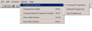
If the Universal type is chosen then you will be
presented with the programming dialog.
|
|
|
|
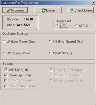
Note : The type of PIC to
program is automatically extracted from the DEVICE directive used in the
BASIC code. The default fuse settings are taken directly from the hex file
produced by the compiler. However, you have the choice of manipulating the fuses manually when
the programmer window appears.
To program the PIC, simply click on the Program
button, not forgetting to choose the printer port that your programmer is attached
to.
If
the EPICtm option is chosen, you will be asked for the location of
its working directory. This needs only to be done once, as the compiler saves
the information permanently. If EPIC’s working directory changes, then you can
alter these details by choosing Options->Change Epic Details.
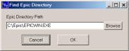
Note : The EPICtm
software must already be installed on your machine. And you must own the EPICtm
programmer that accompanies it. The LET PIC BASIC editor does not have
the EPIC software built in. It merely allows EPIC to be run from the compiler.
The Universal programmer is not compatible with EPIC’s software, and
EPIC’s hardware is not compatible with the Universal programmer software.
Another option is that of any programmer of choice.
In order for the compiler’s IDE to run the
programmer, it must be told some details about it by choosing Options->Change
External Programmers details.
|
|
|
|
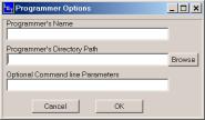
As in the Epictm setup, this is required
only once, because the compiler saves the details.
The programmer is only available after a successful
compile has been carried out. The programming button ![]() will them become unshaded.
will them become unshaded.
If the BASIC program is already loaded into the
editor and a change in the EPIC’s path or an external programmer is carried
out. The BASIC program must be loaded in again.