THIS DOCUMENT IS PROVIDED TO THE USER ''AS IS''. Etc.etc.
All information in this document is to the best of my knowledge.
The 8051 PL/M51 software is used in applications using 2*16, 2*20, 4*20 and 2*40 LC-Displays.
The PIC ASM software is used in applications using 2*20, 4*20 and 2*40 LC-Displays.
So there should be no risk, but there's still Murphy.
Uuuhm..
The pin assignment shown in
Table 2.1. is the industry standard for character
LCD-modules with a
maximum of 80 characters.
The pin assignment shown in
Table 2.2. is the industry standard for character
LCD-modules with
more than 80 characters.
To be sure
always check the manufacturers datasheet!
To locate pin 1 on a module check the manufacturers datasheet!
Table 2.1., Pin assignment for <= 80 character displays
| Pin number |
Symbol |
Level |
I/O |
Function |
| 1 |
Vss |
- |
- |
Power supply (GND) |
| 2 |
Vcc |
- |
- |
Power supply (+5V) |
| 3 |
Vee |
- |
- |
Contrast adjust |
| 4 |
RS |
0/1 |
I |
0 = Instruction input
1 = Data input |
| 5 |
R/W |
0/1 |
I |
0 = Write to LCD module
1 = Read from LCD module |
| 6 |
E |
1, 1->0 |
I |
Enable signal |
| 7 |
DB0 |
0/1 |
I/O |
Data bus line 0 (LSB) |
| 8 |
DB1 |
0/1 |
I/O |
Data bus line 1 |
| 9 |
DB2 |
0/1 |
I/O |
Data bus line 2 |
| 10 |
DB3 |
0/1 |
I/O |
Data bus line 3 |
| 11 |
DB4 |
0/1 |
I/O |
Data bus line 4 |
| 12 |
DB5 |
0/1 |
I/O |
Data bus line 5 |
| 13 |
DB6 |
0/1 |
I/O |
Data bus line 6 |
| 14 |
DB7 |
0/1 |
I/O |
Data bus line 7 (MSB) |
Table 2.2., Pin assignment for > 80 character displays
| Pin number |
Symbol |
Level |
I/O |
Function |
| 1 |
DB7 |
0/1 |
I/O |
Data bus line 7 (MSB) |
| 2 |
DB6 |
0/1 |
I/O |
Data bus line 6 |
| 3 |
DB5 |
0/1 |
I/O |
Data bus line 5 |
| 4 |
DB4 |
0/1 |
I/O |
Data bus line 4 |
| 5 |
DB3 |
0/1 |
I/O |
Data bus line 3 |
| 6 |
DB2 |
0/1 |
I/O |
Data bus line 2 |
| 7 |
DB1 |
0/1 |
I/O |
Data bus line 1 |
| 8 |
DB0 |
0/1 |
I/O |
Data bus line 0 (LSB) |
| 9 |
E1 |
1, 1->0 |
I |
Enable signal for row 0 and 1 (1stcontroller) |
| 10 |
R/W |
0/1 |
I |
0 = Write to LCD module
1 = Read from LCD module |
| 11 |
RS |
0/1 |
I |
0 = Instruction input
1 = Data input |
| 12 |
Vee |
- |
- |
Contrast adjust |
| 13 |
Vss |
- |
- |
Power supply (GND) |
| 14 |
Vcc |
- |
- |
Power supply (+5V) |
| 15 |
E2 |
1, 1->0 |
I |
Enable signal for row 2 and 3 (2ndcontroller) |
| 16 |
n.c. |
|
|
|
Table 2.3. HD44780 instruction set
| Instruction |
Code |
Description |
Execution time** |
| RS |
R/W |
DB7 |
DB6 |
DB5 |
DB4 |
DB3 |
DB2 |
DB1 |
DB0 |
| Clear display |
0 |
0 |
0 |
0 |
0 |
0 |
0 |
0 |
0 |
1 |
Clears display and returns cursor to the home position (address 0). |
1.64mS |
| Cursor home |
0 |
0 |
0 |
0 |
0 |
0 |
0 |
0 |
1 |
* |
Returns cursor to home position (address 0). Also returns display being shifted to the original position. DDRAM contents remains unchanged. |
1.64mS |
| Entry mode set |
0 |
0 |
0 |
0 |
0 |
0 |
0 |
1 |
I/D |
S |
Sets cursor move direction (I/D), specifies to shift the display (S). These operations are performed during data read/write. |
40uS |
| Display On/Off control |
0 |
0 |
0 |
0 |
0 |
0 |
1 |
D |
C |
B |
Sets On/Off of all display (D), cursor On/Off (C) and blink of cursor position character (B). |
40uS |
| Cursor/display shift |
0 |
0 |
0 |
0 |
0 |
1 |
S/C |
R/L |
* |
* |
Sets cursor-move or display-shift (S/C), shift direction (R/L). DDRAM contents remains unchanged. |
40uS |
| Function set |
0 |
0 |
0 |
0 |
1 |
DL |
N |
F |
* |
* |
Sets interface data length (DL), number of display line (N) and character font(F). |
40uS |
| Set CGRAM address |
0 |
0 |
0 |
1 |
CGRAM address |
Sets the CGRAM address. CGRAM data is sent and received after this setting. |
40uS |
| Set DDRAM address |
0 |
0 |
1 |
DDRAM address |
Sets the DDRAM address. DDRAM data is sent and received after this setting. |
40uS |
| Read busy-flag and address counter |
0 |
1 |
BF |
CGRAM / DDRAM address |
Reads Busy-flag (BF) indicating internal operation is being performed and reads CGRAM or DDRAM address counter contents (depending on previous instruction). |
0uS |
| Write to CGRAM or DDRAM |
1 |
0 |
write data |
Writes data to CGRAM or DDRAM. |
40uS |
| Read from CGRAM or DDRAM |
1 |
1 |
read data |
Reads data from CGRAM or DDRAM. |
40uS |
Remarks:
- DDRAM = Display Data RAM.
- CGRAM = Character Generator RAM.
- DDRAM address corresponds to cursor position.
- * = Don't care.
- ** = Based on F
osc = 250kHz.
Table 2.4. Bit names
| Bit name |
Setting / Status |
| I/D |
0 = Decrement cursor position |
1 = Increment cursor position |
| S |
0 = No display shift |
1 = Display shift |
| D |
0 = Display off |
1 = Display on |
| C |
0 = Cursor off |
1 = Cursor on |
| B |
0 = Cursor blink off |
1 = Cursor blink on |
| S/C |
0 = Move cursor |
1 = Shift display |
| R/L |
0 = Shift left |
1 = Shift right |
| DL |
0 = 4-bit interface |
1 = 8-bit interface |
| N |
0 = 1/8 or 1/11 Duty (1 line) |
1 = 1/16 Duty (2 lines) |
| F |
0 = 5x7 dots |
1 = 5x10 dots |
| BF |
0 = Can accept instruction |
1 = Internal operation in progress |
Shown after reset (with N=0).

Table 2.5. DDRAM address usage for a 1-line LCD
| Display size |
Visible |
| Character positions |
DDRAM addresses |
| 1*8 |
00..07 |
0x00..0x07 |
| 1*16 |
00..15 |
0x00..0x0F |
| 1*20 |
00..19 |
0x00..0x13 |
| 1*24 |
00..23 |
0x00..0x17 |
| 1*32 |
00..31 |
0x00..0x1F |
| 1*40 |
00..39 |
0x00..0x27 |
Shown after reset (with N=1).

Table 2.6. DDRAM address usage for a 2-line LCD
| Display size |
Visible |
| Character positions |
DDRAM addresses |
| 2*16 |
00..15 |
0x00..0x0F + 0x40..0x4F |
| 2*20 |
00..19 |
0x00..0x13 + 0x40..0x53 |
| 2*24 |
00..23 |
0x00..0x17 + 0x40..0x57 |
| 2*32 |
00..31 |
0x00..0x1F + 0x40..0x5F |
| 2*40 |
00..39 |
0x00..0x27 + 0x40..0x67 |
Shown after reset (with N=1).

Table 2.7. DDRAM address usage for a 4-line LCD
| Display size |
Visible |
| Character positions |
DDRAM addresses |
| 4*16 |
00..15 |
0x00..0x0F + 0x40..0x4F + 0x14..0x23 + 0x54..0x63 |
| 4*20 |
00..19 |
0x00..0x13 + 0x40..0x53 + 0x14..0x27 + 0x54..0x67 |
| 4*40 |
(00..39) on 1st controller and
(00..39) on 2nd controller |
(0x00..0x27 + 0x40..0x67) on 1st controller and
(0x00..0x27 + 0x40..0x67) on 2nd controller |
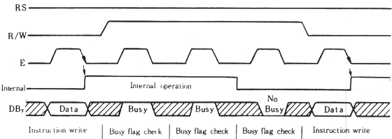
Example of busy flag testing using an 8-bit interface.

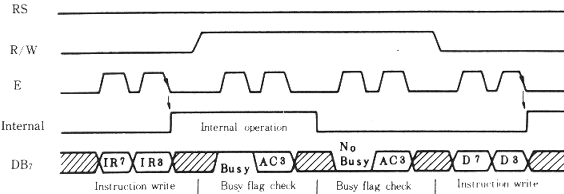
Example of busy flag testing using a 4-bit interface.

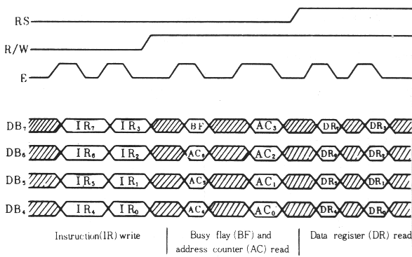
Example of data transfer using a 4-bit interface.

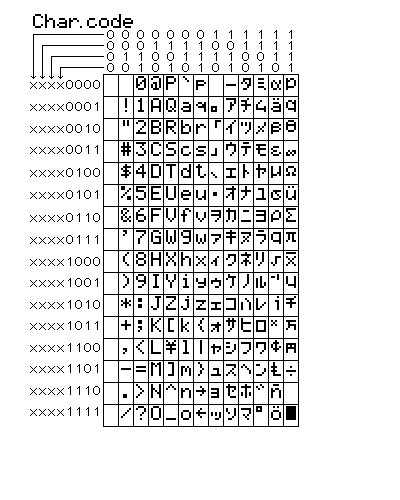
Characterset for 5x7 dot font


Found DDRAM addresses 0x00..0x07 + 0x40..0x47 to be functional for a 1*16 display size.
Make/model: not mentioned / SC1601AS*B.
[2] Hendrik Abma:
Found DDRAM addresses 0x00..0x07 + 0x40..0x47 to be functional for a 1*16 display size.
Make/model: Samtron / KP-03.
[3] Luigi Candurro:
Found DDRAM addresses 0x00..0x07 + 0x40..0x47 to be functional for a 1*16 display size.
Make/model: Crystal Clear Technology / CMC116-01.
[4] Thierry Giorgetti:
Found DDRAM addresses 0x00..0x07 + 0x40..0x47 to be functional for a 1*16 display size.
Make/model: Xiamen Ocular / GDM1601c (Local copy available as zipped file, approx 278kB).